


Regency FG39 FireGenie Freestanding Gas Stove
15
INSTALLATION
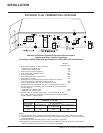
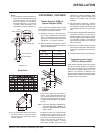
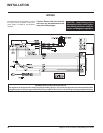
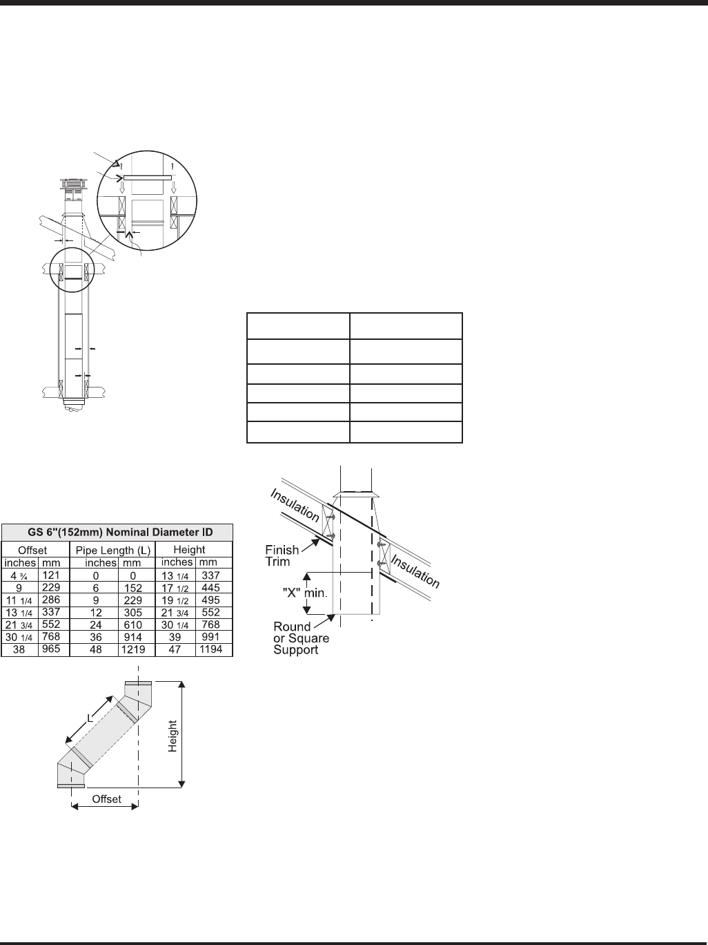
Offset Chart
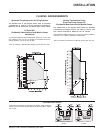
Diagram 13
Notes:
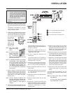
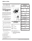
a) For multistorey vertical installations, a
Ceiling Fire stop (Part # 963) is required
at the second floor, and any subse-
quent floor. Diagram 13. The opening
should be framed to 10 " x 10" (254mm
x 254mm) inside dimensions, in the
same manner as shown in diagram 10.
b) Any occupied areas above the first floor,
including closets and storage spaces,
through which the vertical flue passes,
must be enclosed.
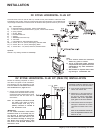
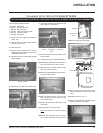
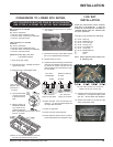
CATHEDRAL CEILINGS
Round Support (RDS) &
Square Support (SQS)
If your home has a cathedral ceiling (no attic
space between the ceiling and the roof), install
the chimney and support as follows.
1) Situate the chimney in a convenient loca-
tion as near as possible to the appliance
outlet. Cut and frame a hole in the roof for
the support. The sides of this hole must be
vertical with 1 1/4" (32mm) clearance.
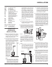
2) Place the support in the opening. Lower it
to the correct height as determined by the
table and diagram below.
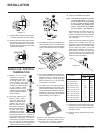
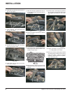
Using a level, make sure the support is
vertical. If the support extends above the
roof, cut it flush with the top of the roof. Nail
the support to the frame opening using (8)
3" (76mm) spiral nails or #8 x 1-1/2" (38mm)
screws.
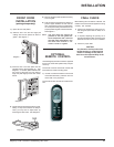
Note: If you are using a 6" square sup-
port you may find it difficult to
screw it in place because it is fairly
small inside.
Simpson Dura-Flue has provided angle
brackets with this support which can be
screwed to the outside of the support box
and nailed to surrounding framing as re-
quired. Use a minimum of four #8 x 1/2"
(13mm) screws per bracket. In some
cases these brackets may need to be
trimmed (e.g.: to fit under a flashing). Place
the Finish Collar around the support and
fasten it to the ceiling using the screws
provided.
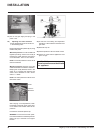
3) Use appropriate roof flashing. Place the
flashing under the upper shingles and on
top of the lower shingles approximately half
of the flashing should be under the shin-
gles.
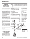
4) Assemble the desired lengths of Black Pipe
and Elbows necessary to reach from the
appliance adaptor up through the support
box and flashing to proper height as per Dia.
12, local codes or page 9. Ensure that all
pipe and elbow connections are in their fully
twist lock position.
5) Ensure flue is vertical and secure flashing
to the roof with roofing nails. Slide the storm
collar over the pipe section and seal with a
mastic.
6) Twist lock the flue cap on to the last section.
Support Extensions - Round
(RDSE) or Square (SQSE)
Steep pitched cathedral ceilings may require
the use of a support extension. This piece fits
down inside the support and can be adjusted
to increase the support's length by up to 22"
(559mm). The extension is attached to the
support using the eight metal screws provided.
Be sure there is at least a 2 inch overlap where
the extension joins the support.
Slope "X"
0/12 -2/12 4" (102mm)
2/12 -7/12 5-1/2" (140mm)
7/12 -12/12 6-3/4" (172mm)
12/12-24/12 7-1/2" (191mm)
24/12+ 12-1/2" (378mm)
1-1/4" (32mm) Min.
1-1/4" (32mm) Min.
1-1/4"
(32mm)
Min.
1-1/4" (32mm) Min.
nails
Ceiling Firestop