


14
Regency FG39 FireGenie Freestanding Gas Stove
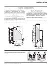
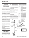
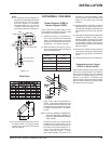
Diagram 11: The upper half of the flashing is
installed under the roofing material and not
nailed down until the chimney is installed.
This allows for small adjustments.
4) Assemble the desired lengths of black pipe
and elbows necessary to reach from the
appliance adaptor up though the Round
Support Box. Insure that all pipes and
elbow connections are in the fully twist-
locked position and sealed.
5) Cut a hole in the roof centred on the small
drilled hole placed in the roof in Step 2. The
hole should be of sufficient size to meet the
minimum requirements for clearance to com-
bustibles of 1-1/4" (32mm) . Slip the flashing
under the shingles (shingles should overlap
half the flashing) as per diagram 11.
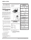
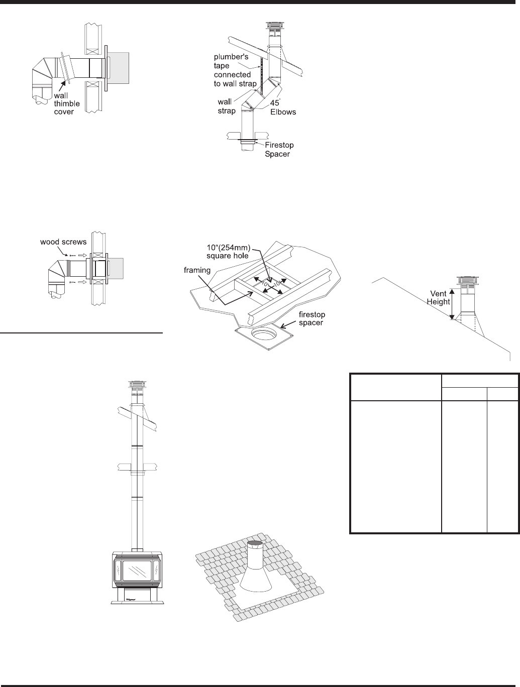
Diagram 12
7) Ensure flue is vertical and secure the base
of the flashing to the roof with roofing rails,
slide storm collar over the pipe section and
seal with a mastic.
8) Install the vertical termination cap by twist
locking it.
6) Continue to assemble pipe lengths.
Note: If an offset is necessary in the attic
to avoid obstructions, it is impor-
tant to support the flue pipe every
3 feet, to avoid excessive stress
on the elbows, and possible sep-
aration. Wall straps are available
for this purpose. See diagram 7.
Galvanized pipe and elbows may be uti-
lized in the attic as well as above the
roofline. The galvanized finish is desirable
above the roofline due to its higher corro-
sion resistance.
Continue to add pipe sections through the
flashing until the height of the flue cap
meets the minimum height requirements
specified in diagram 12 or local codes. Note
that for steep roof pitches, the vertical
height must be increased. A poor draft, or
down drafting can result from high wind
conditions near big trees or adjoining roof
lines, in these cases, increasing the flue
height may solve the problem.
Roof Pitch Minimum Flue Height
Feet Meters
flat to 7/12 2 0.61
over 7/12 to 8/12 2 0.61
over 8/12 to 9/12 2 0.61
over 9/12 to 10/12 2.5 0.76
over 10/12 to 11/12 3.25 0.99
over 11/12 to 12/12 4 1.22
over 12/12 to 14/12 5 1.52
over 14/12 to 16/12 6 1.83
over 16/12 to 18/12 7 2.13
over 18/12 to 20/12 7.5 2.29
over 20/12 to 21/12 8 2.44
Diagram 10
Diagram 9
Diagram 8
Diagram 7
Diagram 6
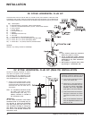
DURA-FLUE VERTICAL
TERMINATION
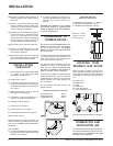
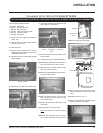
1) Maintain the 1-1/4" (32mm)
clearances (air spaces) to
combustibles when pass-
ing through ceilings, walls,
roofs, enclosures, attic rafter,
or other nearby combustible
surfaces. Do not pack air spac-
es with insulation. Check
page 9 for the maximum ver-
tical rise of the fluing system
and the maximum horizontal
offset limitations.
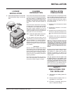
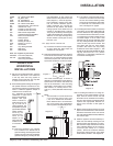
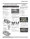
3) To install the Round Support Box/Wall Thim-
ble in a flat ceiling, cut a 10 inch square hole
in the ceiling centred on the hole drilled in
Step 2. Frame the hole as shown in diagram
10.
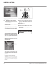
INSTALLATION
7) Install the Wall Thimble in the center of the
10" square and attach with wood screws.
8) Slide the decorative wall thimble up to the
wall surface being careful not to scratch
the paint and attach with screws provid-
ed. Apply decorative brass or chrome trim
if desired. See diagram 7.
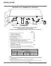
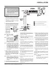
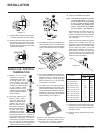
2) Set the gas appliance in its
desired location. Drop a
plumb bob down from the
ceiling to the position of the
appliance flue exit, and
mark the location where
the flue will penetrate the
ceiling. Drill a small hole at
his point. Next, drop a
plumb bob from the roof to
the hole previously drilled
in the ceiling, and mark the
spot where the flue will penetrate the roof.
Determine if ceiling joists, roof rafters or
other framing will obstruct the fluing sys-
tem. You may wish to relocate the appli-
ance or to offset, as shown in diagram 9 to
avoid cutting load bearing members.