


7Regency
®
E21-3 Gas Fireplace Insert
INSTALLATION
POLICY FOR SOLID
FUEL BURNING &
FACTORY BUILT
FIREPLACES
The Regency
®
E21 may be installed and vented
into any solid fuel fi replace that has been installed
in accordance with the National, Provincial and
local building codes and is constructed of non-
combustible materials.
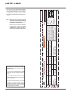
1) Installer must mechanically attach the sup-
plied label to the inside of the fi rebox of the
fi replace into which the gas fi replace insert
is installed.
2) Do not cut any sheet-metal parts of the
fi replace, in which the gas fi replace insert
is to be installed.
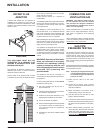
3) If the factory-built fi replace has no gas access
hole(s) provided, an access hole of 1-1/2"
(37.5mm) or less may be drilled though the
lower sides or bottom of the fi rebox in a proper
workmanship like manner. This access hole
must be plugged with a non-combustible
insulation after the gas supply line has been
installed.
4) The fi replace fl ue damper can be fully blocked
open or removed for installation of the gas
fi replace insert.
5) The fi replace and fi replace chimney must
be clean and in good working order and
constructed of non-combustible materials.
6) The chimney cleanouts must fi t properly.
7) Refractory (fi rebricks), glass doors, screen
rails, screen mesh and log grates can be
removed from the fi replace before installing
the gas fi replace insert.
8) Smoke shelves, shields and baffl es may be
removed if attached by mechanical fasteners.
If any part is removed it must not weaken
the structural integrity of the factory built.
9) Trim panels or surrounds shall not seal
ventilation openings in the fi replace.
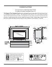
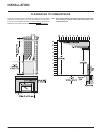
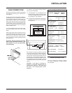
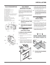
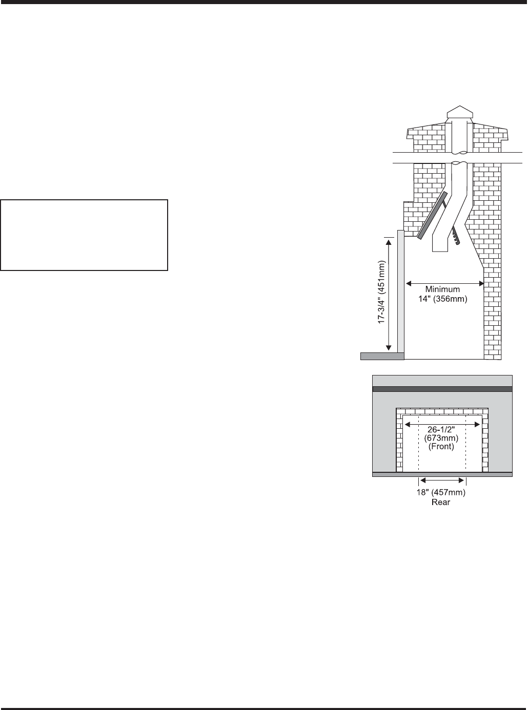
MINIMUM FIREPLACE
CLEARANCES
Diagram shows the minimum fi replace opening
required to be able to install the Regency
®
gas
fi replace insert.
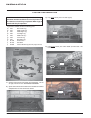
INSTALLATION
CHECKLIST
1) Locate your appliance. Refer to the "Clear-
ances to Combustibles" and "Minimum
Fireplace Clearances" sections.
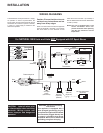
2) Make gas and electrical connections. Refer
to the "Gas Connection" section.
Test the pilot. Must be as per diagram in the
"Valve Description" section.
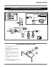
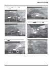
3) Install Flue Connector. Refer to the "Flue
Connector Installation" section.
4) Install vent. Refer to the "Venting" section.
5) Test Gas pressure. Refer to the "Gas Pipe
Pressure Testing" section.
Check aeration. Refer to the "Gas Insert
Aeration System" section.
6) Test for fl ue spillage. Refer to the "Test for
Flue Spillage" section.
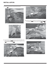
7) Install standard and optional features. Refer
to the following sections where applicable:
a. Brick Panel
b. Faceplate & Trim
c. Flush Glass
d. Flush Louver
e. Bay Front
f. Full Screen Doors
g. Remote Control
h. Wall Switch
i. Wall Thermostat
8) Final check. Refer to the "Final Check"
section.
Before leaving this unit with the customer,
the installer must ensure that the appliance is
fi ring correctly and operation fully explained to
customer.
This includes:
1) Clocking the appliance to ensure the correct
fi ring rate (rate noted on label) after burning
appliance for 15 minutes.
2) If required, adjusting the primary air to ensure
that the fl ame does not carbon. First allow
the unit to burn for 15-20 min. to stabilize.
3) Ensure that the appliance is venting
correctly.
CAUTION: Any alteration to the product that
causes sooting or carboning that results
in damage is not the responsibility of the
manufacturer.
Note: If you are installing the Molded Faceplate,
the minimum fireplace dimensions are as
follows:
Width (at front): 29-1/8" (740mm)
Depth: 15" (381mm)
Height: 18-5/8" (473mm)
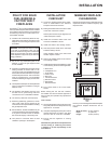
"WARNING: This fi replace has been converted
for use with a gas fi replace insert only and
cannot be used for burning wood or solid fuels
unless all original parts have been replaced,
and the fi replace re-approved by the authority
having jurisdiction."