


18 Regency
®
E21-3 Gas Fireplace Insert
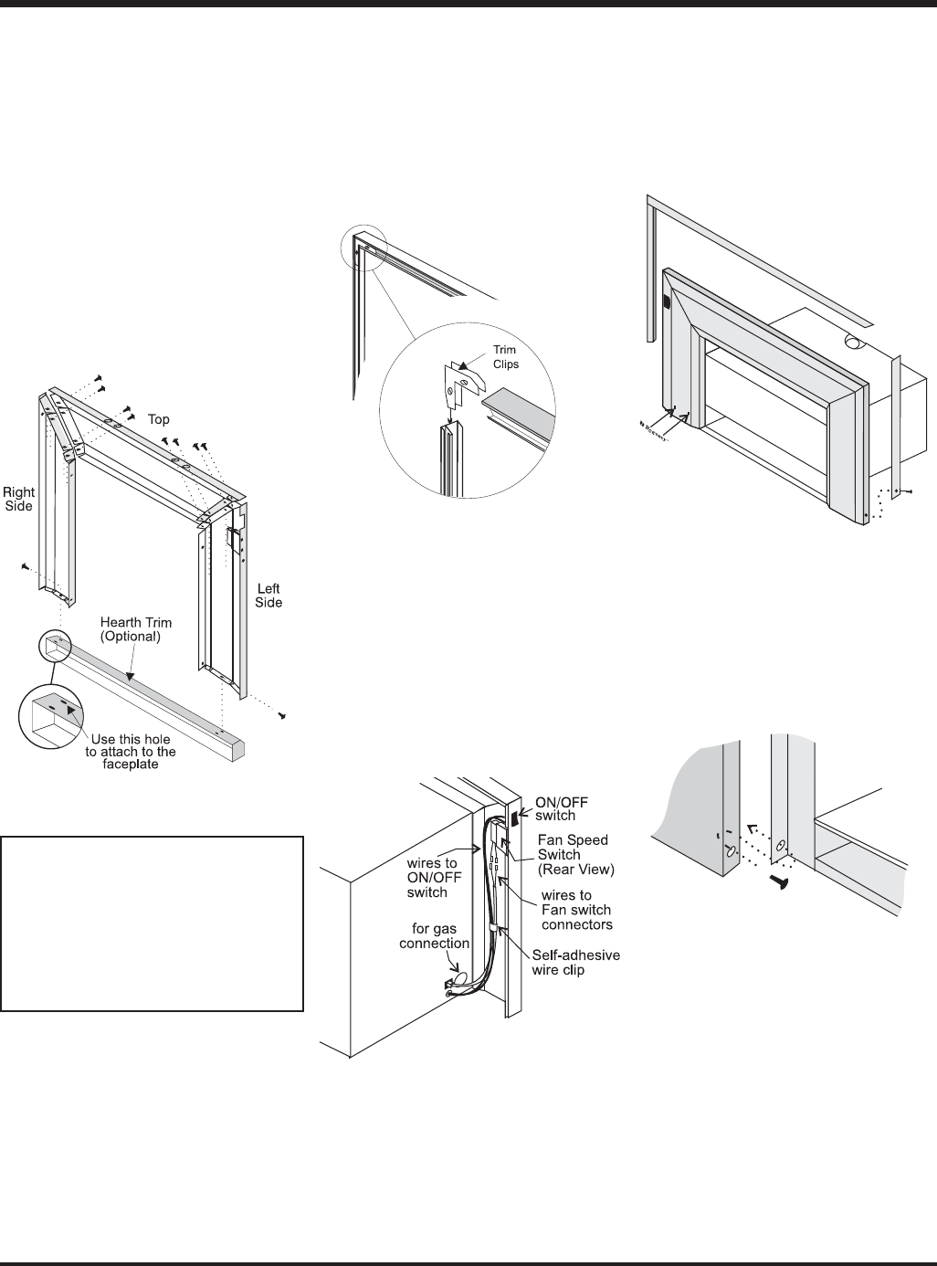
Diagram 4
Diagram 5
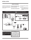
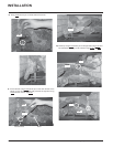
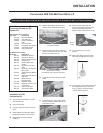
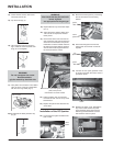
6) Connect the ON/OFF switch wires by taking
the black and red wires with the female
ends and connecting them to the ON/OFF
switch.
Diagram 3
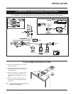
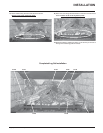
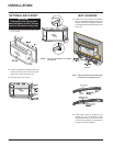
8) The power cord should be run behind the
faceplate panel.
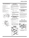
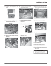
9) Attach the brass trim to the faceplate by
drilling a 1/8" hole through into the faceplate
using the hole in the trim as a guide. Fasten
the trim to the faceplate panels using the
gold plated screws. See diagram 4.
7) Tuck the wires into the faceplate to keep
them away from the insert using the clip
provided. Attach the clip to the rear of the
faceplate to ensure that the wires do not
touch the side of the unit. See diagram 3.
10) Attach the faceplate panels to the insert
body using the 4 remaining black screws.
See diagram 5.
11) Push the logo plate into the two holes in
the bottom left corner of the faceplate. See
diagram 4.
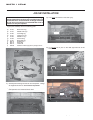
FACEPLATE & TRIM
INSTALLATION
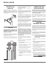
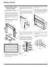
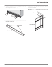
1) Lay the faceplate panels fl at, face down on
something soft so they don't scratch.
2) Take the top faceplate and align the holes
in it with the holes in the side panels. Using
the screws provided, attach from the top of
the panel (the holes in the top panel are
slightly larger than the holes in the side
panel to facilitate easier installation). See
diagram 1.
Hint: Don't tighten the trim to the bottom of
the faceplate side panels with the screws
provided. See diagram 1.
Diagram 1
Diagram 2
4) Place the trim on the assembled faceplate
panels, aligning the wire connections from
the switches with the notch on the left side
panel.
5) Connect the fan switch wires by taking the
black and red wires with the male ends (in
the grey harness) and connect them with
the wire connectors from the fan speed
control.
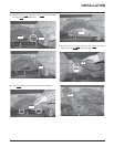
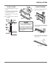
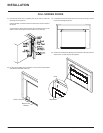
Hearth Trim Option: Hearth Trim is an option
that can be used to fi nish off the installation when
the bottom of the fi replace is higher than the
hearth or to raise the fi replace. Lay the faceplate
side panels fl at, face down on something soft
so they don't scratch. Attach the Hearth Trim to
the bottom of the faceplate side panels with the
screws provided. See Diagram 2. Now attach
the assembled pieces to the insert body.
3) Using the connectors provided, join the left
side trim (with the ON/OFF switch) to the
top trim. See diagram 2. Connect the right
side trim to the top trim.
INSTALLATION