


13Regency
®
E21-3 Gas Fireplace Insert
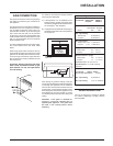
TEST FOR
FLUE SPILLAGE
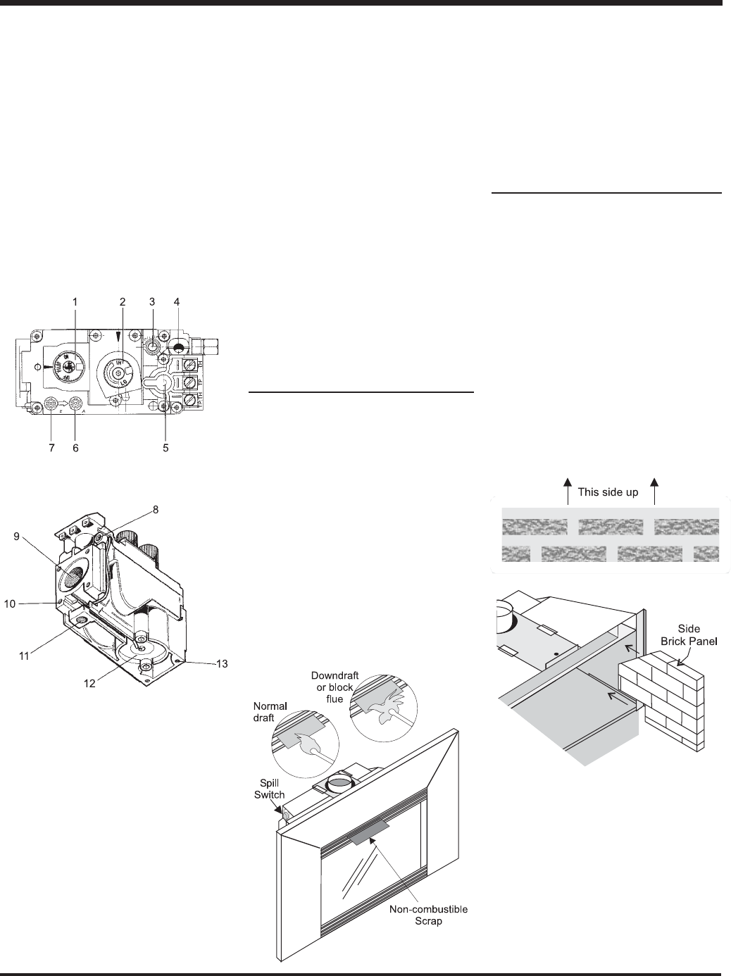
A " spillage" test must be made before
the installed unit is left with the customer.
Follow the procedure below:
1) Close all external doors and windows in
the house.
2) Light the unit and set controls to maximum.
Turn fan to OFF on unit.
3) After fi ve minutes, test that there is a “pull”
on the fl ue by placing a smoking match,
cigarette or similar device which gives
off smoke, in front of the upper part of
the louver. To ensure a valid test, place
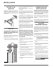
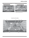
GAS INSERT
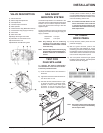
AERATION SYSTEM
The aeration adjustment rod is attached to the
air shutter which is located just above the orifi ce
bracket. The rod is used to adjust the aeration
on the main burner without having to take the
appliance apart.
The burner aeration is factory set but may need
adjusting due to either the local gas supply, air
supply or altitude.
Natural Gas: 1/8" open
Propane: 5/16" open
Note: Any damage due to carboning
resulting from improperly setting
the aeration controls is NOT covered
under warranty.
Note: Aeration Adjustment should only be
performed by an authorized Regency
®
Installer at the time of installation or
service.
a scrap piece of sheet metal (or other
noncombustible material) in the upper louver,
this will prevent the natural convection of the
unit from interfering with the test.
Note: The smoke should be drawn into the
louver. If the smoke is still not drawn
in, turn the unit off and check for the
cause of the lack of draft. If necessary,
seek expert advice.
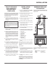
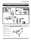
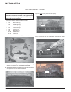
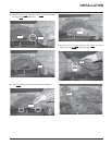
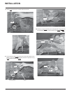
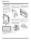
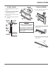
OPTIONAL
BRICK PANEL
1) Unwrap the brick pattern panels from the
protective wrapping.
2) With the glass removed, position the
back panel fi rst (see diagram for correct
positioning), then the two side panels. Slide
the side brick panel into place from the front
of the fi rebox, there is a tab at the top of the
unit to hold the side panels in place.
3) The brick panels should be tight against
the fi rebox sides and back. The side panels
should be fl ush with the glass.
Note: Use caution when sliding side panels
in as they can easily be scratched by
the brick panel tabs.
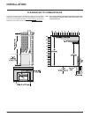
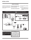
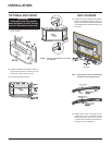
VALVE DESCRIPTION
1) Gas on/off knob
2) Manual high/low adjustment
3) Pilot Adjustment
4) Thermocouple Connection
5) Main Operator
6) Outlet Pressure Tap (Manifold Pressure)
7) Inlet Pressure Tap (Supply Pressure)
8) Pilot Outlet
9) Main Gas Outlet
10) Flange Securing Screw Holes
11) Alternative TC Connection Point
12) Thermoelectric Unit
13) Additional Valve Mounting Hole
INSTALLATION