


22 Regency
®
E21-3 Gas Fireplace Insert
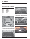
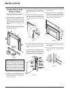
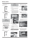
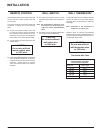
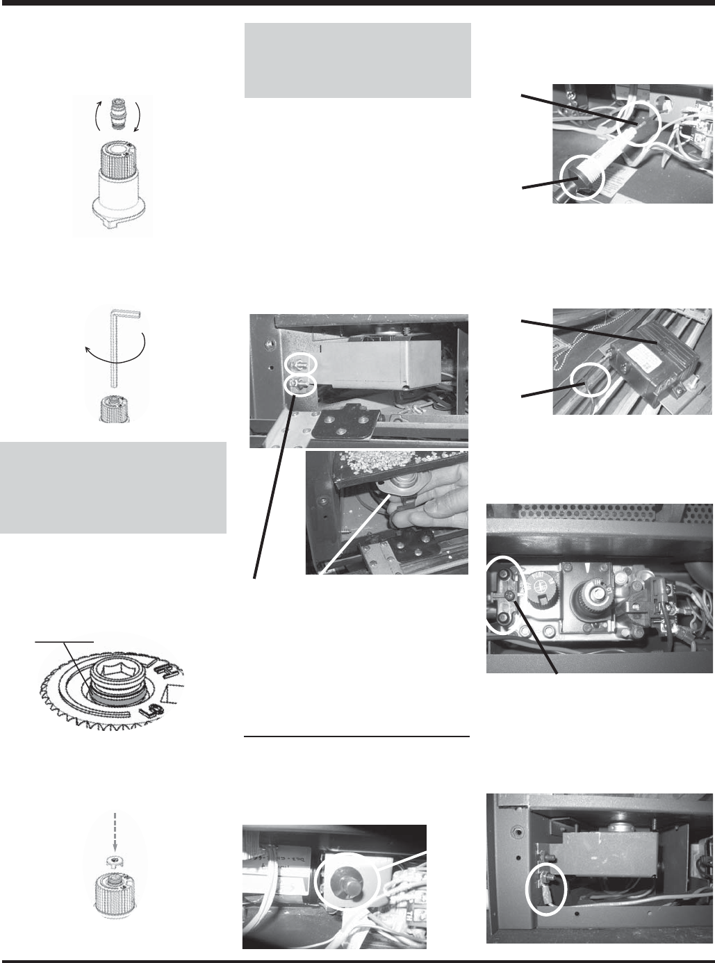
17) Verify that if the conversion is from NG to
LPG, the screw must be re-assembled
with the red o-ring visible (Fig. 5).
18) Re-assemble the black protection cap
(Fig. 6).
WARNING!
Also check that the pilot and main
burner injectors
are appropriate for the gas type.
LPG Configuration
Red o-ring visible
Fig.5
Fig. 6
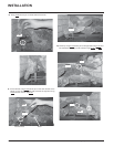
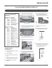
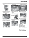
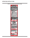
Installation of the DC Sparker:
24) Locate the Piezo Ignitor situated at the
side of valve.
25) Remove the Piezo Ignitor by unscrewing
the nut at the back of the mounting
bracket.
26) Disconnect the ignitor wire from the
Piezo Ignitor and connect it to the DC
Sparker.
Piezo
Ignitor
Ignitor
Wire
Piezo
Ignitor
Ignitor
Wire
DC
Sparker
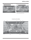
27) Connect the DC spark generator wires
to the SIT Valve with the screw, which is
provided in the kit.
28) Reattach the switch cover. Reinstall the
top 11/32 nut star washer into place.
Then install the ground wire onto the
bottom lug and reinstall the 11/32 nut
star washer to secure in place.
22) Attach the label "This unit has been
converted to LPG" near or on top of the
serial # decal.
23) Replace the yellow "NG" label with red
"LPG" label.
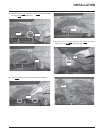
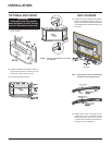
19) Replace Burner Tray and reverse steps
6) to 1).
20) Adjust the burner aeration setting from
1/8" to 3/16" as required for the best
fl ame picture.
21) Remove the switch cover from the left
side of the body base. Disconnect the 2
wires from the thermodisc and pull the
thermodisc out of the bracket under the
left side of the fi rebox bottom. Replace
with the Thermodisc supplied with this
kit and reconnect the 2 wires.
Remove the 2 nuts holding the switch box in
place, then pull the
thermosdisc out of the bracket.
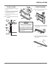
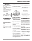
16) Using the Allen wrench as shown in
Fig.4, rotate the screw clockwise until
snug, do not overtighten.
Fig.4
WARNING!
Do not overtighten the screw.
Recommended to
grip the wrench by the short side.
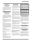
14) Check that the screw is clean and if
necessary remove dirt.
15) Flip the screw (Fig. 3).
Fig.3
Screw
INSTALLATION