


26 Regency CLASSIC C34-2 Direct Vent Freestanding Gas Heater
CAUTION
Any alteration to the product that caus-
es sooting or carboning that results
in damage to the unit is not the re-
sponsibility of the manufacturer and
will not be covered by the warranty.
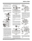
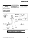
OPTION 1: REMOTE
CONTROL
INSTALLATION
Use the Regency Remote Control Kit approved
for this unit. Use of other systems may void
your warranty.
The remote control kit comes with a hand held
transmitter, a receiver and a wall mounting
plate.
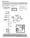
1) Choose a convenient location on the wall
to install the receiver (protection from
extreme heat is very important). Run
wires from the fireplace to that location.
Use the Thermostat Wire Table.
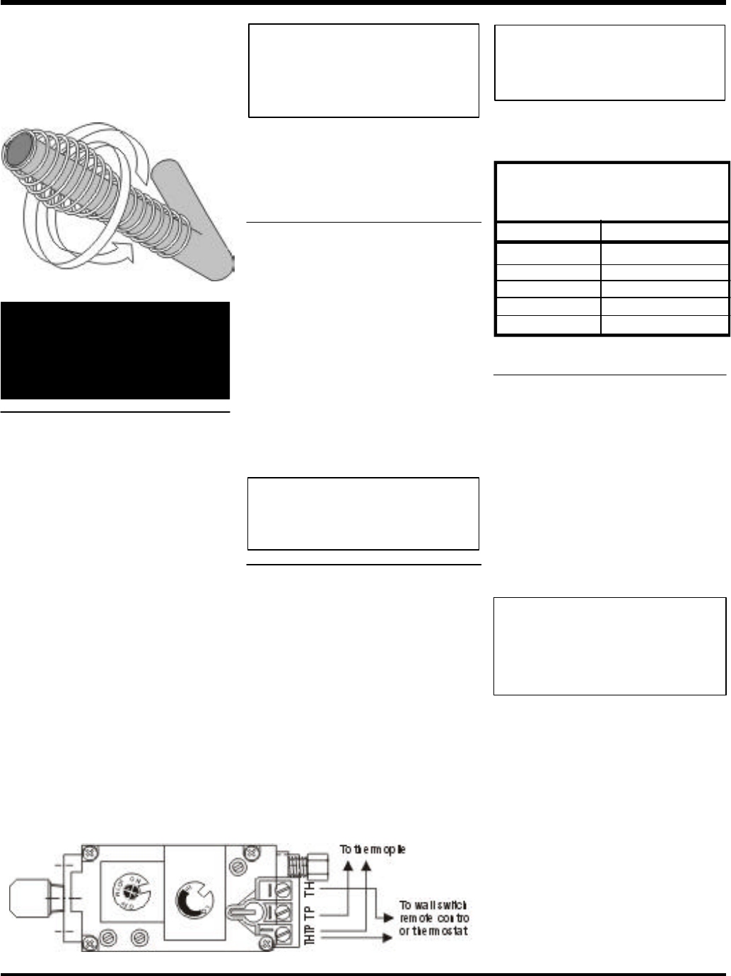
2) Connect the two wires to the gas valve.
See diagram below.
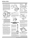
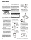
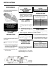
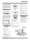
DOOR HANDLE
Attach spring handle by rotating counter clock-
wise onto rod. Ensure that the spring fits into
the entire length of the rod.
DO NOT TRY TO TURN
DOOR HANDLE!
IT IS NOT DESIGNED
TO BE MOVED.
CAUTION
Do not wire millivolt remote
control wires to the
120V AC wires
3) Install 3 AAA alkaline batteries in transmitter
and 4 AA alkaline batteries in the receiver.
Install the receiver and its cover in the wall.
Switch the remote receiver to "remote"
mode. The remote control is now ready for
operation.
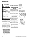
OPTION 2: REMOTE
WALL SWITCH
1) Run the wire through the opening in the rear
of the unit. Be careful not to damage any
wires.
Note: We recommend a maximum of 15'
of wire but if you wish to go with a
longer run use the Thermostat Wire
Table.
2) Connect the wire to the wall switch and
install into receptacle box.
CAUTION
Do not wire millivolt wall switch
for gas appliance to the 120V AC
wires
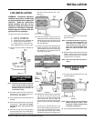
OPTION 3: WALL
THERMOSTAT
INSTALLATION
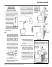
Regency offers an optional programmable ther-
mostat but any 250-750 millivolt rated non-
anticipator type thermostat that is CSA, ULC or
UL approved may be used.
Connect the wires as per the wiring diagram.
Use the Thermostat Wire Table to determine the
maximum wire length.
FINAL CHECK
Before leaving this unit with the customer, the
installer must ensure that the appliance is firing
correctly. This includes:
1) Clocking the appliance to ensure the correct
firing rate (rate noted on label) at 15 minutes.
2) If required, adjusting the primary air to en-
sure that the flame does not carbon. First
allow the unit to burn for 15 min. to stabilize.
3) Check for proper draft.
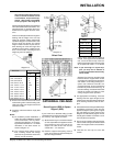
14 GA.
16 GA.
18 GA.
20 GA.
22 GA.
50 Ft.
32 Ft.
20 Ft.
12 Ft.
9 Ft.
Recommended Maximum Lead Length
(Two-Wire) When Using Wall
Thermostat (CP-2 System)
Wire Size Max. Length
Thermostat Wire Table
INSTALLATION
CAUTION
Do not wire millivolt wall thermo-
stat wires to the 120V AC wires
Note: Preferable if the thermostat is
installed on an interior wall.