


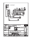

22
Shut gas and power off to the unit, close the system
off and drain the heater. Remove the draft diverter.
Remove the access panel and jacket top. Lift flue
collector off. Remove “V” baffles over tube(s) to be
replaced. If no pipe unions have been provided, use the
header as a union, remove the flange nuts off the inlet-
outlet header, break gas connection and slide heater
away from piping to allow room to work. Pull wedge clips
out of control wells and remove sensing bulbs. Remove
flange nuts of the return header and remove header. Lift
heat exchanger straight up and out.
Inspect “O” ring seals at this time. Unless severed,
they are reusable. The tube may be cut out with a
hacksaw or hammer and chisel adjacent to both tube
sheets, leaving studs in the tube sheets. Then proceed
to collapse studs in the tube sheets with a chisel or
screwdriver. Use caution not to cut into the tube sheet.
Replacement tubes will have the fins stripped off longer
on one end. The long end is inserted into the opening of
the tube sheet first; then the short end is fitted through the
opposite tube sheet. If the tube ends become dented or
bent, straighten at least (4) inches back from the tube and
by means of a tapered punch.
Insert tube roller into tube opening up to stop against
tube, then push center rod in until roller is tight. Be careful
to keep replacement tube squared up 1/8” outside each
tube sheet. A loose tube will sometimes pull toward the
roller. Attach drill motor to tube roller, holding it straight
and level. Proceed to expand tube until the tool begins to
grab. At this point, 1/2” to 1” should be expose on the tool
shank. Reverse drill motor or wrench out by hand. Care
should be exercised to avoid applying excessive torque
during rolling operation and to avoid thinning out any part
of the tube wall excessively over 015’. Use same
procedure at the opposite end of the tube.
Apply line pressure test, and re-roll, if necessary,
before reassembly of the heater.
DESOOTING PROCEDURE
CAUTION: SOOT IS COMBUSTIBLE. EXERCISE
EXTREME CARE.
Soot will clog areas between fins and cause eventual
tube failure. Any sign of soot at the base of the burners
or around the outer jacket indicates a need for cleaning.
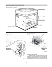
1. Remove top and flue collector from cabinet.
2. Remove “V” baffles from heat exchanger.
3. Remove burner drawer. (See burner tray
removal).
4. Take garden hose and wash heat exchanger,
making sure soot is removed from between
fins. (Avoid excessive water against
refractory).
5. Reassemble-When heater is fired, some steam
will form from wet refractory. This is normal.
NOTE: In extreme cases it may be necessary to remove
the heat exchanger completely for cleaning. The
simplest method is steam cleaning at the local car
wash. DO NOT WIREBRUSH.
COMBUSTION CHAMBER REMOVAL
To remove combustion chamber, you must first have
removed the heat exchanger. Unbolt metal combination
chamber retainer from top and remove combustion
chamber panels individually.
REFACTORY PANELS TOP VIEW
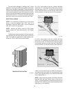
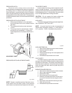
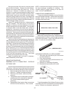
CONTROL IMMERSION WELL REPLACEMENT
Remove top, sensing bulb and clip. Collapse well tube
at the open end with a chisel, push through into header
and remove the header. Insert a new well and roll into
place. If a roller is not available, solder.
IMMERSION WELL
Fig. # 8126.0
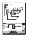
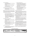
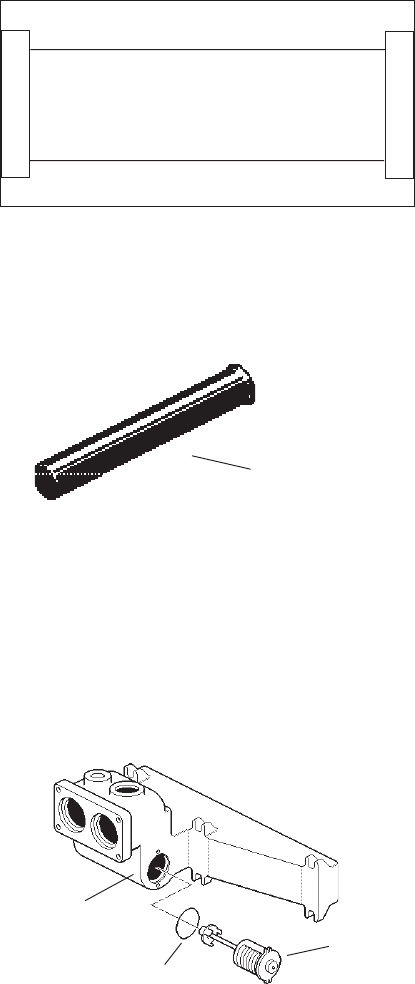
UNITHERM GOVERNOR (U.G.) REPLACEMENT
1. Shut water, gas and electricity off, close valves
and relieve pressure.
2. Drain heat exchanger.
3. Loosen and remove (2) bolts that secure U.G.
Assembly to header.
4. Remove U.G. Assembly with gasket.
5. Reverse above procedure to re-install.
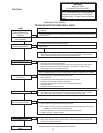
INLET/OUTLET
HEADER
UNITHERM
U.G. GASKET GOVERNOR
Fig. #8224.0
To test the operation of the Unitherm Governor, place
in hot water (over 100°F) and watch for movement against
spring. If there is not movement, replace unit.