PIPE SIZING FOR GAS CONNECTIONS
MAXIMUM EQUIVALENT PIPE LENGTH
Natural gas 1000 BTU/Ft .60 Specific Gravity @ 0.5” W.C. Pressure Drop
Propane Gas 2500 BTU/Ft 1.53 Specific Gravity @ 0.6” W.C. Pressure Drop
1/2” 1” 1-1/4” 1-1/2” 2” 2-1/2”
N P N P N P N P N P N P
514 - 10 15 35 65 150 130 360 500 - - -
624 - - 10 25 45 100 95 250 340 - - -
724 - - - 20 35 80 75 180 260 600 - -
824 - - - 15 25 60 55 130 185 480 500 -
PLUMBING FOR WATER CONNECTIONS
LOCATION
The heater requires water flow and positive pressure
to fire and operate properly. It must therefore be installed
downstream of the discharge side of the filter pump. A
typical installation is plumbed as follows:
1. The inlet side of the filter is plumbed directly to
the discharge side of the filter pump;
2. The outlet side of the filter is then plumbed to
the inlet of the heater; and
3. The outlet of the heater is plumbed to the return
line to the pool or spa. The pump, filter and
heater are thus plumbed in series.
Heater must be located so that any water leaks will not
damage the structure of adjacent area. High temperature
plastic pipe (CPVC) may be connected directly into the
heater if local codes permit and if controls operate the
pump for at least fifteen minutes after the heater is turned
off.
CAUTION: NEVER install PVC directly into heater.
Four feet of copper or high temperature pipe and two
elbows are required between the heater and the PVC
connections
Fig. #8129.0
12
When local codes permit the use of less than four feet
high temperature piping or two elbows, provisions should
be made to always shut the heater off a minimum of 15
minutes prior to pump shut down in order to carry away
residual heat and prevent damage to the low temperature
piping. A fireman switch included in the time clock may
be used for this purpose with instruction not to override
this sequence manually. See wiring diagram section for
electrical hookup location of the fireman switch in the
electrical circuit.
NOTE: 1. When 2” piping is used into the heater, this
piping must be anchored (copper) or screwed into the
flange (metal) if operating pressures above 30 PSI are
encountered.
2. Any restrictions between heater outlet and
pool will void the warranty.
FLOW RATES
MODEL PIPE SIZE MIN. GPM MAX. GPM
514 2” 60 120
624 2” 60 120
724 2” 60 120
824 2” 60 120
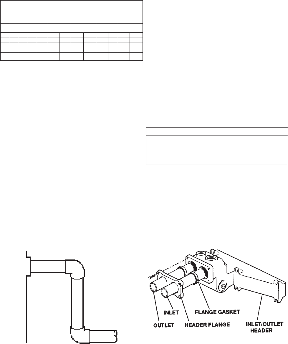
COMPANION FLANGE CONNECTIONS
DO NOT use petroleum base assembly fluids (such as
Petroleum Jelly or lubricating oil). If assembly tube is
required use a silicone base such as Armoral etc.
The inlet/outlet header flange accepts a 2” copper
tube as a slip connection directly into the header. The
flange is also thread for a 2” copper male threaded
adapter.
Fig. # 8221.0
3
3


