


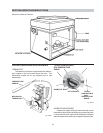
GAS VALVE REMOVAL
1. Shut off gas supply to the heater. Remove gas
piping to gas valve inlet.
2. Disconnect wires, pilot tubing and bleed line, if
required.
3. Turn vertical gas pipe from manifold slightly
and unscrew gas valve.
4. Reverse above procedure to re-install.
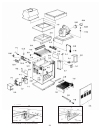
MAIN BURNER AND ORIFICE REMOVAL
1. Remove burner drawer. See burner drawer
removal procedure.
2. Remove screws and burner hold down bracket.
NOTE: If the heat exchanger is sooted badly, the burner
hold down bracket and spacer can become distorted
from direct flame impingement and this usually neces-
sitates replacement of these parts.
3. Lift burners from slotted spacers and slide from
orifices. Clean with a wire brush.
4. Orifices usually do not need to be replaced. To
clean, run either copper wire or wood toothpick
through orifice. Do not enlarge hole. To
remove orifice, use a socket wrench and re-
move from manifold. DO NOT over tighten
when reinstalling.
PILOT REMOVAL AND CLEANING
1. Remove burner drawer. (See burner drawer
removal procedure).
2. Disconnect pilot tubing, disconnect wires from
gas valve.
3. Disconnect pilot bracket from burner shield.
4. Remove pilot form bracket.
5. Remove pilot orifice and air opening, and clean
with wire or small brush. CAUTION! DO NOT
enlarge hole in pilot orifice.
6. Reverse above procedure to re-install.
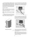
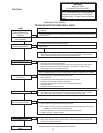
HEAT EXCHANGER REMOVAL
1. Shut water, gas and electricity off, close valves
and relieve pressure, remove relief valve.
Remove side inspections panels.
2. Remove top holding screws.
3. Remove draft diverter, lift and remove top and
flue collector. Remove inspection panels.
4. Loosen bolts and disconnect flange nuts on
inlet-outlet header, loosen union(s) at gas pipe
and slide boiler away from piping until stud
clear the header.
5. Remove heat exchanger corner brackets.
6. Remove combustion chamber slips at the four
corners of the heat exchanger.
7. Lift heat exchanger straight up using caution
not to damage refractory.
8. Reverse above procedure to reinstall.
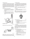
TUBE CLEANING PROCEDURE
Establish a regular inspection schedule frequency,
depending on local water condition and severity of
service. Do not let the tubes clog up solidly. Clean out
deposits over 1/16” in thickness.
The heater may be cleaned from the right side,
without breaking pipe connections. If is preferable,
however, to remove both headers for better visibility
through the tubes and to be sure the ground-up lime dust
does not get into the system.
Note that you do not remove the top panel or the heat
exchanger, generally.
After reaming, mount the wire brush in place of the
auger and clean out debris remaining in the tubes.
Another method is to remove the heat exchanger,
ream tubes and immerse heat exchanger in non-inhibited
de-scale solvent for sever scale build up.
TUBE REPLACEMENT PROCEDURE
On Raypak units, tube replacement may be effected
without rolling as a temporary means or repair, providing
there are two or more tubes rolled in to act as stays on
the left and right side. The “O” rings should provide a seal
up to 120 PSI working pressure. Use
3/8” heavy duty reversible drill motor or larger to power
the tube roller. If a reversible drill is not available, after
rolling the tube in, remove the drill motor and wrench out
the roller. A tube roller is available from the factory.
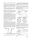
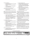
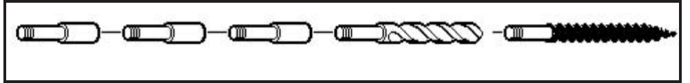
RAYPAK TUBE CLEANING KIT
Extension Pieces (5) Auger with Carbide Tip Wire Brush
Fig. # 8154.0
21