AUTOMATIC CHLORINATORS AND CHEMICAL FEED-
ERS
All chemicals must be introduced and completely
diluted into the pool or spa water before being circulated
through the heater. Do not place chlorine tablets or
bromine sticks in the skimmer. High chemical concen-
trations will result when the pump is not running (i.e.
overnight).
Chlorinators must feed downstream of the heater and
have an anti-siphoning device to prevent chemical back-
up into the heater when the pump is shut off.
NOTE: High chemical concentrates from feeders and
chlorinators that are out of adjustment will cause very
rapid corrosion to the heat exchanger in the heaters.
Such damage is not covered under the warranty.
UNITHERM GOVERNOR OPERATION
The patented Unitherm Governor is a thermostatic
mixing valve specifically designed to maintain constant
heater internal temperature between 105°F to 115°F
despite continually changing flow rated from the filter and
changing pool temperatures. This narrow range is
needed to prevent damaging condensation on the burn-
ers which will occur if the heater runs for any length of
time below 100°F. It is also needed to inhibit scale
formation in the tubes by maintaining temperatures well
below accelerated scaling temperatures.
EXTERNAL AUXILIARY BYPASS VALVE
(Where Required)
An auxiliary bypass valve should be used when flow
rates exceed 115 GPM (usually a high performance
pump size larger than two HP will exceed this flow rate).
This valve is required to complement the function of the
automatic bypass valve, particularly when starting the
heater in winter or early spring when the spa or pool
temperature is down below 55°F. It also serves to
eliminate needless pressure drop through the heat and
accompanying reduction in the flow rate to the spa jets,
etcetera.
FROM TO
HEATER HEATER
TO POOL FROM
POOL
Fig. # 8150.0
AUXILIARY BYPASS VALVE ADJUSTMENT
13
To set bypass: with clean filter, adjustment is made
by feeling the inlet and outlet pipes at the heater. Outlet
pipes should be slightly warmer than inlet and comfortable
to the touch. If pipe is hot, close bypass; if cold open
bypass.
The heater is also equipped with a manual bypass
built into the header. This is in addition to the automatic
bypass valve. This may be used with flow rates up to 120
GPM and adjusted as below.
NOTE: Sooting or liming caused by improper bypass
adjustment voids the warranty
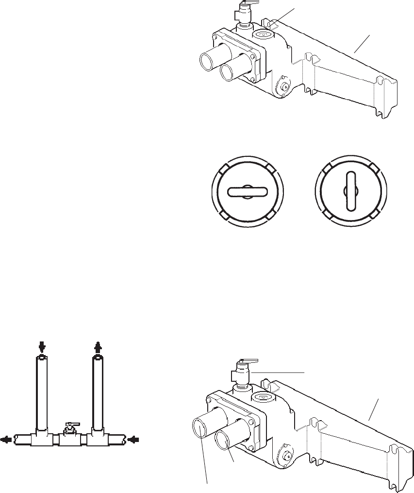
BYPASS VALVE
INLET/OUTLET
HEADER
Fig. # 8223.0
MANUAL BYPASS ADJUSTMENT
OPEN POSITION CLOSED POSITION
Fig. # 8222.0
PRESSURE RELIEF VALVE INSTALLATION
To conform to local building codes, it may be
necessary to install a pressure relief valve. A 3/4”
pressure relief valve having a capacity equal to BTU/HR
output of the model to be installed is recommended for this
appliance.
A 3/4” NPT connection is provided in the inlet/outlet
header for installation of a pressure relief valve. The valve
shall be installed in a vertical position.
PRESSURE RELIEF VALVE
INLET/OUTLET HEADER
INLET
OUTLET
Fig. # 8223.0


