


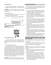
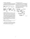
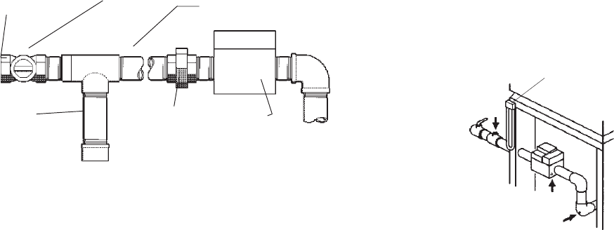
GAS SUPPLY CONNECTIONS
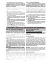
Gas piping must have a sediment trap ahead of the
heater gas controls, and a manual shut off valve located
outside the heater jacket. All gas piping should be tested
after installation in accordance with local codes.
MANUAL SHUT OFF VALVE
GAS INLET HEATER JACKET
SEDIMENT GAS
TRAP UNION VALVE
Fig. #8090.0
CAUTION: the heater and its manual shut off valve
must be disconnected from the gas supply during any
pressure testing of that system at test pressures in
excess of 1/2 Psig (3.45 KPA). Dissipate test pressure
in the gas supply line before reconnecting the heater and
its manual shut off valve to gas supply line. FAILURE
TO FOLLOW THIS PROCEDURE MAY DAMAGE THE
GAS VALVE. OVER PRESSURED GAS VALVES ARE
NOT COVERED BY WARRANTY. The heater and its
gas connections shall be leak tested before placing the
appliance in operation. Use soapy water for leak test.
Do NOT use open flame.
NOTE: Do not use teflon tape on gas line pipe thread.
A flexible sealant is recommended.
A minimum of 7” W.C. and a maximum of 14” W.C.
upstream pressure under load, and no load conditions
must be provided for natural gas or a minimum of 12”
W.C. and a maximum of 14” for propane gas.
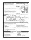
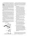
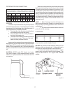
GAS PRESSURE REGULATOR
The gas pressure regulator is preset and sealed at 4”
W.C. for natural gas, and 11” W.C. for propane gas.
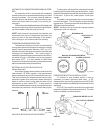
Between the gas valve and the burners is a 1/8” pipe plug.
The pressure at this point, taken with a manometer,
should be about 3.7” W.C. natural gas and 10.5” W.C.
propane gas. If an adjustment is needed, remove seal
and turn adjustment screw clockwise to in-
crease pressure or counter clockwise
to decrease pressure
GAS PRESSURE MANOMETER
TEST UPSTREAM
MANUAL
SHUT-OFF
VALVE
GAS PRESSURE TEST
AT GAS VALVE
GAS PRESSURE TEST
AT HEATER
Fig. # 8149.0
11