


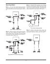

system. Turn on any exhaust fans, such as range
hoods and bathroom exhausts, at maximum
speed. Do not operate summer exhaust fan. Close
fireplace dampers.
4. Place in operation the appliances being inspected.
Follow the manufacturer’s instructions for lighting
each appliance. Adjust thermostat so appliance
will operate continuously.
5. Check the pressure at a pressure tap located 12
in. above the bottom joint of the first vertical vent
pipe. Pressure should be anywhere between -0.01
and -0.08 in. WC.
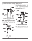
6. After it has been determined that each appliance
remaining connected to the common venting sys-
tem properly vents when tested as outlined above,
return doors, windows, exhaust fans, fireplace
dampers and other gas burning appliances to their
previous conditions of use.
7. Any improper operation of the common venting
system should be corrected so that the installation
conforms with the NFGC (U.S.) or B149 (Canada).
When re-sizing any portion of the common venting
system, the common venting system should be re-
sized to approach the minimum size as
determined using the appropriate tables in Ap-
pendix G in the NFGC (U.S.) or B149 (Canada).
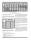
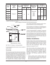
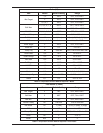
Engineered Vent Systems
Table M provides boiler discharge vent volumes of flue
products at full fire for the calculation of appropriate
vent sizing for common venting.
27
NOTE: Data for 100% firing rate.
Table M: Volume of Flue Products Data
WARNING: Vent connectors serving any other
appliances shall not be connected into any portion of
mechanical draft systems operating under a positive
pressure. If an MVB heater is installed to replace an
existing heater, the vent system MUST be verified to
be of the correct size and Category. If it is NOT, it
MUST be replaced.
NOTE: For extractor sizing, typical CO
2
levels are
8.5% for natural gas and 9.5% for LP gas and flue
temperature of 350° F.
Model
No.
Vent Size
(in.)
Volume of
Flue Products
(CFM)
504 8 170