


20
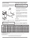
The MVB 504-1504 heaters are wired for 120 VAC, 12
amps while the MVB 2004 heaters are wired for 120
VAC, 18 amps. Consult the wiring diagram shipped
with the heater. Before starting the heater, check to
ensure proper voltage to the heater and pump.
Boiler mounted pumps (up to
3
⁄4 hp) get their power
supply directly from the boiler power supply (connec-
tions in rear wiring box). Install a circuit breaker sized
sufficiently for both the heater and the pump. Pumps
larger than
3
⁄4 hp must use a separate power supply
and run the power through the optional pump contac-
tor which is located in the rear wiring box. Use
appropriately-sized wire as defined by NEC, CSA
and/or local codes. All primary wiring should be 125%
of minimum rating.
If any of the original wire as supplied with the heater
must be replaced, it must be replaced with 105°C wire
or its equivalent.
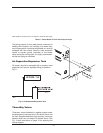
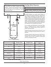
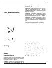
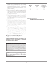
All field wiring connections to the MVB heater are
made inside the rear wiring box as shown in Fig. 16.
Pump power should be taken from terminals 2 (Com),
3 (GND) and 6 (Hot) –
3
⁄4 hp and smaller ONLY. Power
to the MVB heater should be connected to terminals 1,
2, and 3 as noted in Fig. 16. Sensors, interlocks,
Enable/disable, and various options are wired into ter-
minals 1 – 12 as noted in Fig. 16.
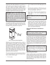
The gas valve pressure regulator on the heater is
nominally preset as noted in Table J.
During normal operation, carbon dioxide should be 8.0
to 9.0% at full fire for natural gas and between 9.0 and
10.0% for propane gas. Carbon monoxide should be
‹100ppm.
Electrical Power Connections
Installations must follow these codes:
• National Electrical Code and any other national,
state, provincial or local codes or regulations hav-
ing jurisdiction.
• Safety wiring must be NEC Class 1.
• Heater must be electrically grounded as required
by the NEC.
• In Canada, CSA C22. 1 C.E.C. Part 1.
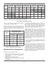
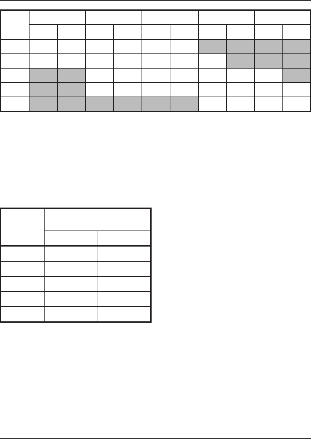
Natural Gas – 1,000 BTU/ft
3
, 0.60 specific gravity at 0.5 in. WC pressure drop
Propane Gas – 2,500 BTU/ft
3
, 1.53 specific gravity at 0.6 in. WC pressure drop
Table I: Maximum Equivalent Pipe Length
NOTE: Manifold pressures should be ±0.2 in. WC.
Table J: Manifold Gas Pressure Settings
Model
No.
1 in. NPT 1-1/4 in. NPT 1-1/2 in. NPT 2 in. NPT 2-1/2 in. NPT
N P N P N P N P N P
504 15 35 65 150 150 360
754 5 15 35 75 70 175 250
1104 15 35 35 75 100 250 225
1504 10 20 20 45 60 150 150 275
2004 35 85 85 200
Model
No.
Manifold Gas Pressure
(High Fire Values)
Natural Gas Propane Gas
504 -0.1 -0.1
754 -0.4 -0.1
1104 -1.0 -0.2
1504 -2.4 -0.6
2004 -2.0 -1.5