


b. Where communicating with the outdoors
through horizontal ducts, each opening shall
have a minimum free area of 1 in.
2
per 2,000
BTUH (1,100 mm
2
per kW) of total input rat-
ing of all equipment in the enclosure.
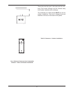
2. One permanent opening, commencing within 12
in. (305 mm) of the top of the enclosure, shall be
permitted where the equipment has clearances of
at least 1 in. (25 mm) from the sides and back and
6 in. (152 mm) from the front of the appliance. The
opening shall directly communicate with the out-
doors or shall communicate through a vertical or
horizontal duct to the outdoors or spaces that
freely communicate with the outdoors, and shall
have a minimum free area of:
a. 1 in.
2
per 3,000 BTUH (740 mm
2
per kW) of
the total input rating of all equipment located in
the enclosure, and
b. Not less than the sum of the areas of all vent
connectors in the confined space.
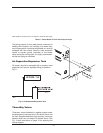
1. Ventilation of the space occupied by the heater
shall be provided by an opening(s) for ventilation
air at the highest practical point communicating
with the outdoors. The total cross-sectional area of
such an opening(s) shall be at least 10% of the
area required in 2. and 3. (below), but in no case
shall the cross-sectional area be less than 10 in.
2
(65 cm
2
).
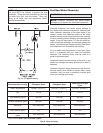
2. For heaters using a barometric damper in the vent
system there shall be a permanent air supply
opening(s) having a cross section area of not less
than 1 in.
2
per 7,000 BTUH (320 mm
2
per kW) up
to and including 1 million BTUH, plus 1 in.
2
per
14,000 BTUH (160 mm
2
per kW) in excess of 1
million BTUH. This opening(s) shall be either
located at or ducted to a point not more than 18 in.
(450 mm) nor less than 6 in. (152 mm) above the
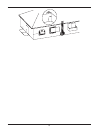
floor level. The duct can also “goose neck” through
12
WARNING: Do not use the “one permanent
opening” method if the equipment room is under
negative pressure conditions.
CAUTION: All combustion air must be drawn from
outside of the building; the mechanical equipment
room must communicate directly with the outdoors.
Canadian Installations
the roof. The duct is preferred to be straight down
and terminated 18 in. (450 mm) from the floor, but
not near piping. This air supply opening require-
ment shall be in addition to the air opening for
ventilation air required in 1. (above).
3. For heaters not using a barometric damper in the
vent system, and when air supply is provided by
natural air flow from outdoors for a power burner
and there is no draft regulator, drafthood or similar
flue gas dilution device installed in the same
space, in addition to the opening for ventilation air
required in 1., there shall be a permanent air sup-
ply opening(s) having a total cross-sectional area
of not less than 1 in.
2
for each 30,000 BTUH (74
mm
2
per kW) of total rated input of the burner(s),
and the location of the opening(s) shall not inter-
fere with the intended purpose of the opening(s)
for ventilation air referred to in 1. This opening(s)
can be ducted to a point not more than 18 in. (450
mm) nor less than 6 in. (152 mm) above the floor
level. The duct can also “goose neck” through the
roof. The duct is preferred to be straight down 18
in. (450 mm) from the floor, but not near piping.
4. Refer to B149 Installation Code for additional
information.
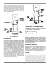
Water Piping
General
The heater should be located so that any water leaks
will not cause damage to the adjacent area or struc-
tures.
WARNING: Care must be taken to ensure that the
equipment room is not under negative pressure
conditions.
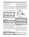
CAUTION: This heater requires forced water
circulation when the burner is operating. See Table F
and Table G for minimum and maximum flow rates
and water pump selection. The pump must be
interlocked with the heater to prevent heater
operation without water circulation.
NOTE: : Minimum pipe size for in/out connections is
2 in. NPT for 504 and 754 models and 2-
1
⁄2 in NPT for
1104 – 2004 models. Verify proper flow rates and ΔT
as instructed in this manual.