


24
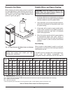
7. The vent terminal requires a 12 in. vent terminal
clearance from the wall.
8. Terminate vent at least 1 ft above grade, including
normal snow line.
9. Multiple direct vent installations require a 4 ft
clearance between the ends of vent caps located
on the same horizontal plane.
Canadian Installations
Refer to latest edition of the B149 Installation code.
A vent shall not terminate:
1. Directly above a paved sidewalk or driveway
which is located between two single-family dwell-
ings and serves both dwellings.
2. Less than 7 ft (2.13 m) above a paved sidewalk or
paved driveway located on public property.
3. Within 6 ft (1.8 m) of a mechanical air supply inlet
to any building.
4. Above a meter/regulator assembly within 3 ft (915
mm) horizontally of the vertical centre-line of the
regulator.
5. Within 6 ft (1.8 m) of any gas service regulator
vent outlet.
6. Less than 1 ft (305 mm) above grade level.
7. Within the 3 ft (915 mm) of a window or door which
can be opened in any building, any non-mechani-
cal air supply inlet to any building or the
combustion air inlet of any other appliance.
8. Underneath a verandah, porch or deck, unless the
verandah, porch or deck is fully open on a mini-
mum of two sides beneath the floor, and the
distance between the top of the vent termination
and the underside of the verandah, porch or deck
is greater than 1 ft (305 mm).
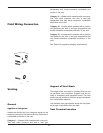
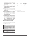
Venting Installation Tips
Support piping:
• horizontal runs - at least every 5 ft
• vertical runs - use braces
• under or near elbows
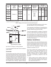
Venting Configurations
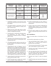
For heaters connected to gas vents or chimneys, vent
installations shall be in accordance with the NFGC
(U.S.), or B149 (Canada), or applicable provisions of
local building codes.
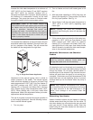
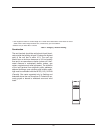
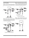
Natural Draft Vertical Venting
(Category I)
Installation
Natural draft venting uses the natural buoyancy of the
heated flue products to create a thermal driving head
that expels the exhaust gases from the flue. The nega-
tive draft must be within the range of -.01 to -.08 in.
WC as measured 12 in. above the appliance flue out-
let to ensure proper operation. Vent material must be
listed by a nationally recognized test agency.
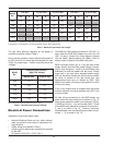
The maximum and minimum venting length for Cate-
gory I appliances shall be determined per the NFGC
(U.S.) or B149 (Canada).
The diameter of vent flue pipe should be sized accord-
ing to the NFGC (U.S.) and B149 (Canada).
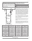
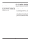
The connection from the appliance vent to the stack
must be as direct as possible. The horizontal breach-
ing of a vent must have an upward slope of not less
than 1/4 inch per linear foot from the heater to the vent
terminal. The horizontal portions of the vent shall also
be supported for the design and weight of the material
employed to maintain clearances and to prevent phys-
ical damage or separation of joints.
WARNING: Examine the venting system at least
once a year. Check all joints and vent pipe
connections for tightness, corrosion or deterioration.
WARNING: The Commonwealth of Massachusetts
requires that sidewall vented heaters, installed in
every dwelling, building or structure used in whole or
in part for residential purposes, be installed using
special provisions as outlined on page 53 of this
manual.