


11
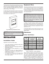
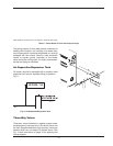
Optional Construction Air Filter
An optional construction air filter is available for use.
The filter should be removed after construction is fin-
ished to allow for unrestricted air flow to the heater.
Direct Vent
If outside air is drawn through the intake pipe directly
to the unit for combustion:
1. Install combustion air direct vent in accordance
with Fig. 24 (horizontal) or Fig. 25 (vertical) of this
manual (pages 28 and 29, respectively).
2. Provide adequate ventilation of the space occu-
pied by the heater(s) by an opening(s) for
ventilation air at the highest practical point com-
municating with the outdoors. The total
cross-sectional area shall be at least 1 in.
2
of free
area per 20,000 BTUH (111 mm
2
per kW) of total
input rating of all equipment in the room when the
opening is communicating directly with the out-
doors or through vertical duct(s). The total
cross-sectional area shall be at least 1 in.
2
of free
area per 10,000 BTUH (222 mm
2
per kW) of total
input rating of all equipment in the room when the
opening is communicating with the outdoors
through horizontal duct(s).
3. In cold climates, and to mitigate potential freeze-
up, Raypak highly recommends the installation of
a motorized sealed damper to prevent the circula-
tion of cold air through the heater during the
non-operating hours.
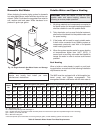
TruSeal™ Combustion Air
In addition to the 3 previous steps, combustion air may
be ducted directly to the heater by using PVC, CPVC
or sealed single-wall galvanized ducting. The duct will
attach directly to the air collar located on the rear of the
heater, using three or four sheet metal screws (not
supplied) equally positioned around the circumference
of the duct. The screen assembly should be removed
before attaching any air duct to the heater. The
screws and duct connection point must be sealed with
RTV (not supplied). TruSeal is generally used when
damaging contaminants are present in the mechanical
room.
All ducting must be self-supported.
Conventional Combustion Air
Supply
U.S. Installations
All Air from Inside the Building
The confined space shall be provided with TWO per-
manent openings communicating directly with an
additional room(s) of sufficient volume so that the com-
bined volume of all spaces meets the criteria for a
room large in comparison (NFGC). The total input of all
gas utilization equipment installed in the combined
space shall be considered in making this determina-
tion. Each opening shall have a minimum free area of
1 in.
2
per 1,000 BTUH (2,225 mm
2
per kW) of the total
input rating of all gas utilization equipment in the con-
fined space, but not less than 100 in.
2
(645 cm
2
). One
opening shall commence within 12 in. (305 mm) of the
top, and one opening shall commence within 12 in.
(305 mm) of the bottom of the enclosure. The mini-
mum dimension of air openings shall be not less than
3 in. (76 mm) in any direction.
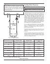
All Air from Outdoors
The confined space shall communicate with the out-
doors in accordance with one of the methods below.
The minimum dimension of air openings shall not be
less than 3 in. (76 mm) in any direction. Where ducts
are used, they shall be of the same cross-sectional
area as the net free area of the openings to which they
connect.
1. Two permanent openings, one commencing
within 12 in. (305 mm) of the top, and one com-
mencing within 12 in. (305 mm) of the bottom of
the enclosure, shall be provided. The openings
shall communicate directly, or by ducts, with the
outdoors or spaces (crawl or attic) that freely com-
municate with the outdoors.
a. Where directly communicating with the out-
doors or where communicating to the
outdoors through vertical ducts, each open-
ing shall have a minimum free area of 1 in.
2
per 4,000 BTUH (550 mm
2
per kW) of total
input rating of all equipment in the enclosure.
CAUTION: Use TruSeal combustion air if
damaging airborne contaminants are or may be
present in the heater area. See the Appendix of this
manual regarding air contamination.