


42
Preparation
Check Power Supply
With multi-meter at incoming power, check voltage
between:
Hot - Common (≈120 VAC)
Hot - Ground (≈120 VAC)
Common - Ground (< 1 VAC)
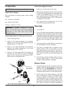
Attach Manometers to Measure Pressures
1. Turn off main gas valve.
2. Attach (1) 12” scale manometer to an upstream
bleedle valve on the gas supply pipe to the boiler
(Measure point “A” in Fig. 35).
3. Attach (1) 12” scale manometer to the manifold
pressure tap located downstream of the valve
(Measure point “D” in Fig. 35).
4. Attach (1) 12” scale manometer to the tapping on
the filter box. Pull black cap from air pressure
switch tee and connect the manometer. NOTE:
Retain caps for reinstallation later.
WARNING: If Common - Ground is > 1 VAC,
STOP: Contact electrician to correct ground failure.
Failure to do this may burn out 120V-24V
transformer, or may cause other safety control
damage or failure.
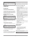
Start-Up
1. Turn power on.
2. Turn on the boiler, approximately 5 seconds after
the blower starts, the igniter should start to spark
(observable through the observation port located
at the front, bottom of the boiler) and the gas valve
will open. Look into the sight glass located at the
bottom of the front panel to check igniter opera-
tion.
3. The boiler ignites at 3000 RPM (as indicated on
the LCD display of the user interface).
4. This boiler is equipped with a standard four-try
ignition module, it will try for ignition up to four
times before going into lockout. If the boiler is
equipped with the optional single-try ignition mod-
ule, it will try for ignition one time before going into
lockout.
5. Wait until the controller indicates 100% on the fir-
ing rate display screen. This will take several
minutes if step modulation is enabled.
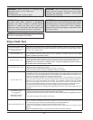
Blower Check
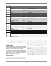
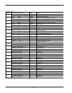
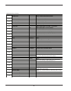
1. Check the high and low fire fan speed on the user-
interface. Enter the service mode by pressing the
UP arrow key and ENTER/MENU key simultane-
ously for 1 second. Verify that the min. and max.
fan speeds match Table R on the following page.
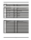
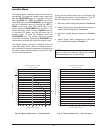
2. Note the high fire air intake pressure on the filter
box and compare to Table Q. Excessively high
pressures indicate an obstruction in the air intake
or undersized/too long air intake ducting. With a
clean air filter in place, record the intake air pres-
sure setting on the start-up checklist. Replace the
filter when the intake air pressure increases by
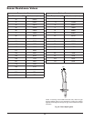
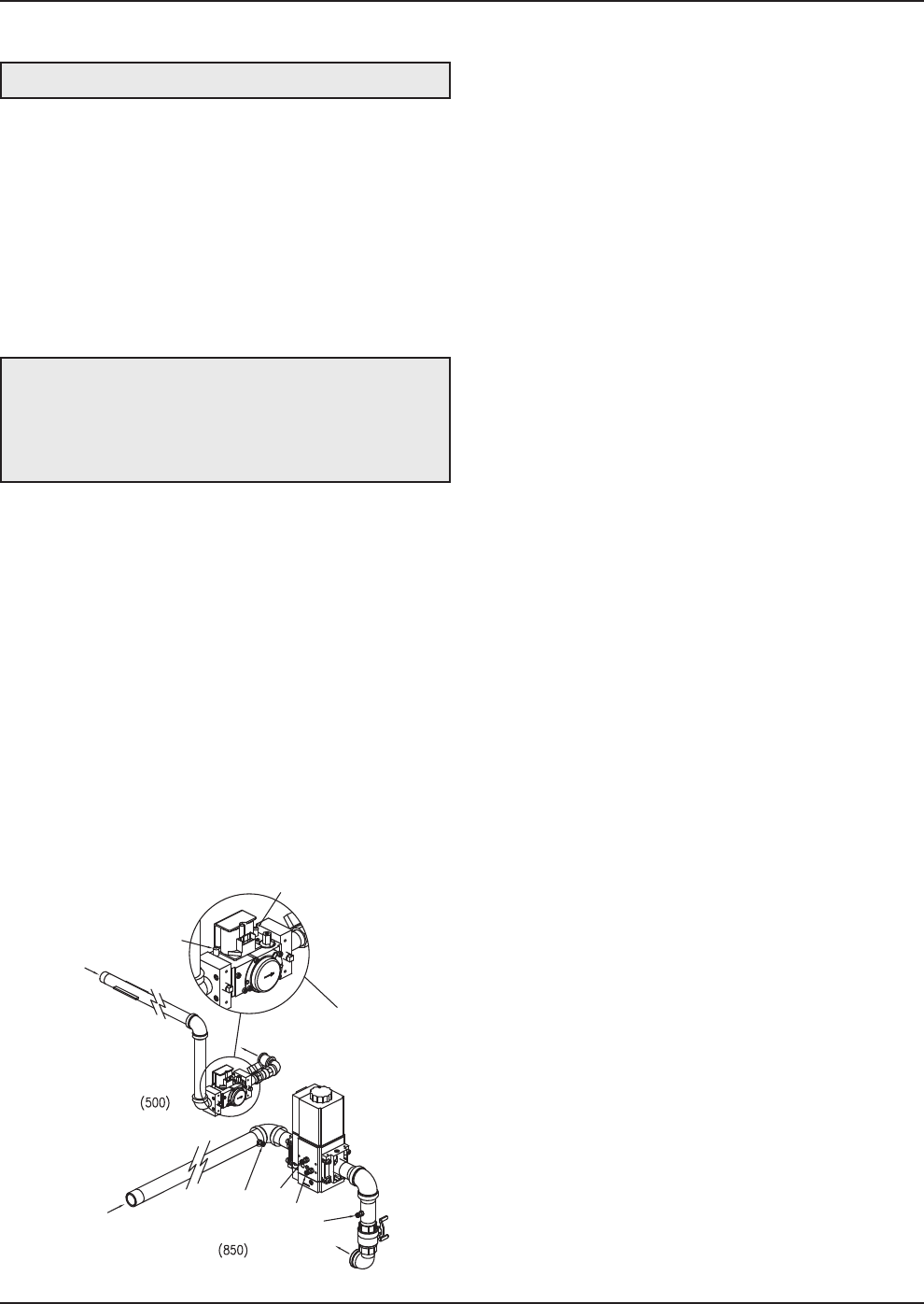
A
A
D
D
B
C
GAS
GAS
TO BURNER
TO BURNER
MODEL 300 VALVE
USES SAME POINTS
A & DAS MODEL 500
Fig. 35: Gas Pressure Measurement Locations
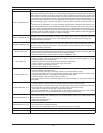
Check Gas Supply Pressure
1. Slowly turn on main gas shut-off valve.
2. Read the gas supply pressure from the manome-
ter; minimum supply pressure for natural gas is 4.0
in. WC, recommended supply is 7.0 in. WC, mini-
mum supply pressure for propane gas is 4.0 in.
WC, recommended supply is 11.0 in. WC (dynam-
ic readings, full fire input).
3. If the gas pressure is greater than 14.0 in. WC,
turn off the main gas shut-off valve.
WARNING: Do not turn on gas at this time.