


23
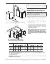
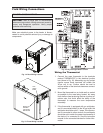
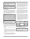
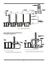
Cascade Follower Pump
and Sensor Wiring
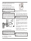
1
. Connect the boiler pump to the terminals marked
BOILER PUMP NEUT (#6), BOILER PUMP HOT
(
#5), and GROUND (#4) at the rear terminal strip.
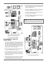
2. If you are using an indirect fired water tank con-
nected directly to the follower boiler, connect the
pump for it to the terminals marked DHW PUMP
NEUT (#8), DHW PUMP HOT (#7), and GROUND
(#3) at the rear terminal strip.
If you desire, an alarm bell or light can be connected
to the alarm contacts of the follower boiler. Optionally,
the normally-closed alarm contact may be used to turn
a device off if the boiler goes into lockout mode. The
alarm contacts are rated 5 amps at 120 VAC.
To connect an alarm device, connect the power for the
device to the ALARM COM terminal. Connect the
alarm device hot wire to the ALARM NO terminal.
Connect the neutral or return of the alarm device to the
neutral or return of the power for the alarm device.
To connect a device that should be powered off during
a boiler lockout condition, follow the same instructions
as above except use the ALARM NC terminal rather
than the ALARM NO terminal.
Note that in a cascade system the alarm output of the
boiler addressed as #1 will also be active if the master
boiler has a lockout condition. The alarm output of boil-
ers addressed as 2–7 will only sound if a lockout
condition occurs on that specific boiler.
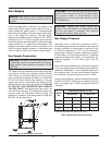
Venting
General
Appliance Categories
Heaters are divided into four categories based on the
pressure produced in the exhaust and the likelihood of
condensate production in the vent.
Category I – A heater which operates with a non-pos-
itive vent static pressure and with a vent gas
temperature that avoids excessive condensate pro-
duction in the vent.
Category II – A heater which operates with a non-pos-
itive vent static pressure and with a vent gas
temperature that may cause excessive condensate
p
roduction in the vent.
C
ategory III – A heater which operates with a positive
vent pressure and with a vent gas temperature that
avoids excessive condensate production in the vent.
Category IV – A heater which operates with a positive
vent pressure and with a vent gas temperature that
may cause excessive condensate production in the
vent.
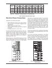
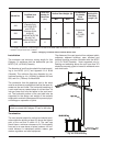
See Table K for appliance category requirements.
Use only approved PVC or CPVC vent materials (in
Canada, ULC-S636 approved plastic materials must
be used) or special gas vent pipes listed for use with
Category IV gas burning heaters, such as the AL29-4C
stainless steel vents offered by Heat Fab Inc. (800-
772-0739), Protech System, Inc. (800-766-3473),
Z-Flex (800-654-5600) or American Metal Products
(800-423-4270). Pipe joints must be positively sealed.
Follow the vent manufacturer’s installation instructions
carefully. Vent installations shall be in accordance with
Part 7, Venting of Equipment, of the NFGC, ANSI
Z223.1/NFPA 54, Section 7, Venting Systems and Air
Supply for Appliances, of the B149 Code, or applicable
provisions of the local building codes.
NOTE: For additional information on appliance
categorization, see the ANSI Z21.13 Standard and
the NFGC (U.S.), or B149 (Canada), or applicable
provisions of local building codes.
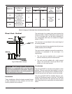
CAUTION: Condensate drains for the vent piping
are required for installations of the XFyre. Follow
vent manufacturer instructions for installation and
location of condensate drains in the vent.
Condensate drain traps must be primed with water to
prevent gas flue leak and must be routed to an
appropriate container for neutralization before dis-
posal, as required by local codes.
CAUTION: Proper installation of flue venting is
critical for the safe and efficient operation of the
boiler.
WARNING: Contact the manufacturer of the vent
material if there is any question about the appliance
categorization and suitability of a vent material for
application on a Category IV vent system. Using
improper venting materials can result in personal
injury, death or property damage.
CAUTION: Raypak recommends the use of a con-
densate neutralizer, sales order option Z-12.