


20
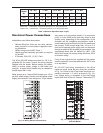
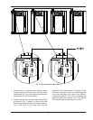
Wiring the Outdoor Sensor
1. There is no connection required if an outdoor sen-
sor is not used in this installation.
2
. If using an Outdoor Sensor, connect the wires for
sensor to the terminals marked OUTDOOR SEN
(shown in Fig. 16) in the electrical junction box.
Caution should be used to ensure neither of these
terminals becomes connected to ground.
3. Use a minimum 22 AWG wire for runs of 100 feet
or less, and minimum 18 AWG wire for runs of up
to 150 feet.
4. Mount the outdoor sensor on an exterior surface of
the building, preferably on the north side in an
area that will not be affected by direct sunlight and
that will be exposed to varying weather conditions.
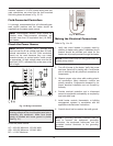
Wiring the Indirect Sensor
1. There is no indirect sensor connection required if
an indirect water heater is not used in the installa-
tion.
2. The XFyre boiler will operate an indirect fired
water heater with either a thermostat type aquas-
tat installed in the indirect tank or a Raypak tank
sensor. When a tank sensor is used, the XFyre
control will automatically detect its presence and a
demand for heat from the indirect water heater will
be generated when the tank temperature falls
below the user settable setpoint by more than the
user selectable offset. The demand will continue
until the sensor measures that the indirect water
heater temperature is above the setpoint.
3. Connect the indirect tank sensor to the terminals
marked DHW SENSOR (shown in Fig. 16) in the
electrical junction box. Caution should be used to
ensure neither of these terminals becomes con-
nected to ground.
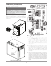
Wiring the Optional 0–10 Volt
Building Control Signal
1. A signal from a building management system may
be connected to the XFyre boiler to enable remote
control. This signal should be a 0–10 volt positive
D
C signal. When this input is enabled using the
installer menu, a building control system can be
used to control either the setpoint temperature or
the heat output of the XFyre boiler. The control
interprets the 0–10 volt signal as follows. When the
signal is between 0 and 1 volt, the XFyre boiler will
be in stand by mode, not firing. When the signal
rises above 1 volt, the XFyre boiler will ignite. As
the signal continues to rise towards its maximum
of 10 volts, the XFyre boiler will increase either in
setpoint temperature or firing rate, depending on
the setting of screen 17 in the installer menu. See
the Installer Menu section for details on the setting
of screens 16 and 17 for this option.
2. Connect a building management system or other
auxiliary control signal to the terminals marked
+0–10 V and -0–10 V in the electrical junction box
(shown in Fig. 16) Caution should be used to
ensure that the +0–10 V connection does not
become connected to ground.
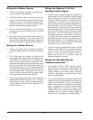
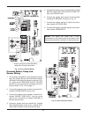
Wiring the Cascade System
Communication Bus
1. Use standard CAT3 or CAT5 computer network
patch cables to connect the communication bus
between each of the boilers. These cables are
readily available at any office supply, computer,
electronic, department or discount home supply
store in varying lengths.
2. It is recommended that the shortest length cable
possible be used to reach between the boilers and
create a neat installation. Do not run unprotected
cables across the floor or where they will become
wet or damaged. Avoid running communication
cables parallel with, or close to or against, high
voltage (120 volt or greater) wiring. Raypak rec-
ommends that the total maximum length of
communication bus cables not exceed 200 feet.