


Page 6
7036-135G
November 22, 2011
R
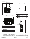
Mt. Vernon Pellet Insert (AE)
• Installation and use of any damaged appliance.
• Modifi cation of the appliance.
• Installation other than as instructed by Hearth & Home
Technologies.
• Installation and/or use of any component part not
approved by Hearth & Home Technologies.
• Operating appliance without fully assembling all
components.
• Operating appliance without legs attached (if supplied
with unit).
• Do NOT Overfi re
Or any such action that may cause a fi re hazard.
WARNING
Hearth & Home Technologies disclaims any
responsibility for, and the warranty will be
voided by, the following actions:
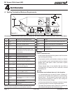
Reciprocating Saw
Channel Locks
Hammer
Phillips Screwdriver
Tape Measure
Plumb Line
Level
Framing Material
Hi-temp Caulking Material
Gloves
Safety Glasses
Framing Square
Electric Drill & Bits (1/4”)
1/4” Self-Tapping Screws
May also need:
Vent Support Straps
Venting Paint
Tools and building supplies normally required
for installation, unless installing into an existing
masonry fi replace:
C. Tools And Supplies Needed
E. Pre-Use Check List
1. Place the appliance in a location near the
fi nal installation area and follow the proce-
dures below:
2. Open the appliance and remove all the parts
and articles packed inside the Component
Pack.
Inspect all the parts and glass for shipping
damage. Contact your dealer if any irregulari-
ties are noticed.
Remove rubber band from ash pan installed for
shipping purposes only.
3. All safety warnings have been read and fol-
lowed.
4. This Owner’s Manual has been read.
5. Floor protection requirements have been met.
6. Venting is properly installed.
7. The proper clearances from the appliance and
chimney to combustible materials have been
met.
8. The masonry chimney is inspected by a profes-
sional and is clean, or the factory built metal
chimney is installed according to the manufac-
turer’s instructions and clearances.
9. The chimney meets the required minimum
height.
10.
All labels have been removed from the glass
door.
11. Plated surfaces have been wiped clean, if
applicable.
12. Wall Control Thermostat has been installed.
13. A power outlet is available nearby.
14. A good quality surge protectory is highly recom-
mended to protect the electronics.
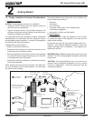
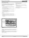
B. Thermostat Wall Control Location
The thermostat wall control’s location will have some affect
on the appliance’s operation.
• Maximum wire length from appliance is 100 feet (30.48m)
continuous unspliced wire. Recommended 20 gauge wire,
solid copper .
• When located close to the appliance, it may require a
slightly higher temperature setting to keep the rest of the
house comfortable.
• When located in an adjacent room or on a different fl oor
level, you will notice higher temperatures near the appli-
ance.
CAUTION!
The wall control is an integral part of the appli-
ance. No other wall control or thermostat can be substi-
tuted.
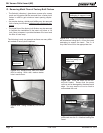
D. Inspect Appliance and Components
WARNING! Risk of Fire! Damaged parts could impair safe
operation. Do NOT install damaged, incomplete or substitute
components.
• Open the appliance and remove all the parts and articles
packed inside the Component Pack. Inspect all the parts
and glass for shipping damage.
• Report to your dealer any parts damaged in shipment.
•
All labels have been removed from the glass door.
•
Plated surfaces have been wiped clean with a soft cloth,
if applicable.
• Read all the instructions before starting the installation.
Follow these instructions carefully during the
installation to ensure maximum safety and benefi t.
• Follow pipe manufacturer instructions for installation
and air clearance requirments.