


Page 24
7036-135G
November 22, 2011
R
Mt. Vernon Pellet Insert (AE)
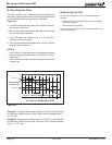
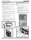
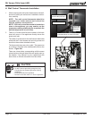
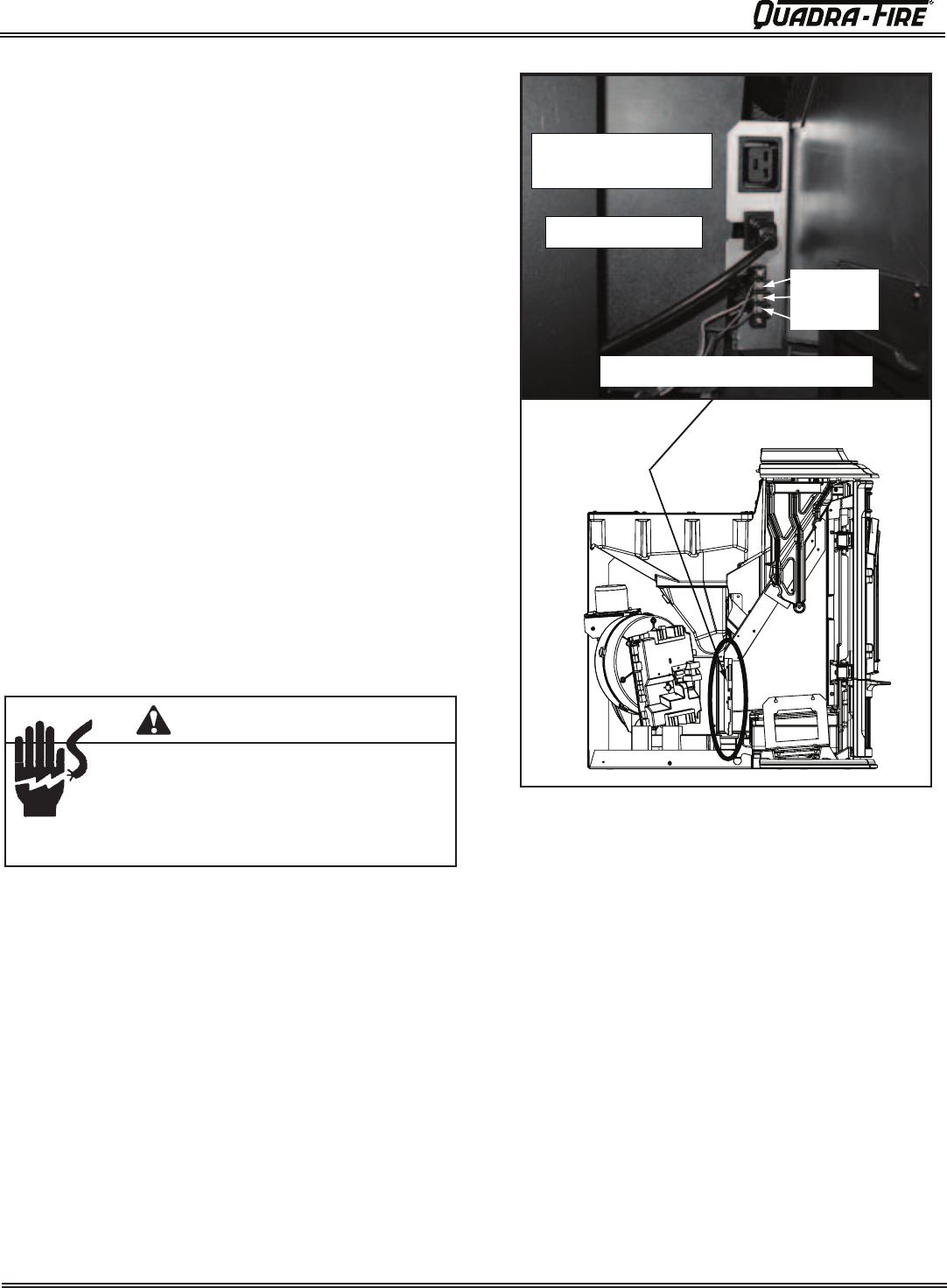
Figure 24.1
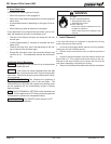
Shock hazard.
• Do NOT remove grounding prong from plug.
• Plug directly into properly grounded 3 prong
receptacle.
• Route cord away from appliance.
•
Do NOT route cord under or in front of appliance.
CAUTION
12 volt Power Inlet (for
optional battery back-up)
Houshold Power Inlet
Green Wire
White Wire
Red Wire
Thermostat Wires in Center 3 Screws
1. When mounting the wall control thermostat on the wall,
be sure to follow your wall control’s installation instruc-
tions carefully.
NOTE: The wall control thermostat should be
mounted on an inside wall and not in direct line
with the appliance convection air.
NOTE: If the wall control thermostat is located too
close to the appliance, you may need to set the
temperature setting slightly higher to maintain the
desired temperature in your home.
2. There is a 5 screw terminal block located on the back
lower left corner of the appliance directly above the
power cord inlet.
The center 3 screws are for the wall control thermostat
wires and the 2 outer screws are mounting screw and
should not have wires attached to them.
The thermostat wires are color coded. The green wire
is on the top, the white in the middle and the red on the
bottom. Figure 24.1.
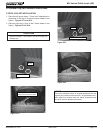
There are colored dots corresponding with the same
colored wire on the right side which are easily seen by
the installer. If by chance it is put in upside down the
dots will be on the left side and will not be visible.
H. Wall Control Thermostat Installation