


Page 23
The electricity to the boiler shall come from a dedicated breaker in the electric
service box. A service switch should be mounted on the side of the boiler so the
burner technician can service the burner and controls. The electrical wiring should
be routed so as not to interfere with normal servicing of the boiler. Wiring done in the
field between devices not attached to boiler shall conform with the temperature
limitations for type T wire (63F/35C) or other specified wire as applicable when
installed in accordance to manufacturer's instructions and wiring diagrams.
If an external electrical source is utilized, the boiler, when installed, must be
electrically bonded to ground in accordance with the requirements of the authority
having jurisdiction or, in the absence of such requirements, with the National
Electrical Code, ANSI/NFPA 70 and/or the Canadian Electrical Code Part 1, CSA
C22.1, Electrical Code.
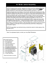
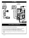
Since the boiler is equipped with a swinging burner door, the supplied 48”
long burner wiring harness with 4-prong quick disconnect plug needs to be used.
The short end of the wiring harness needs to be wired to the burner following the
respective burner wiring diagram in the subsequent pages of this manual. The long
end of the wiring harness needs to be wired into the burner service switch located at
the installers discretion.
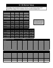
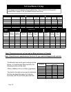
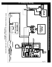
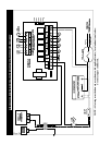
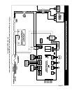
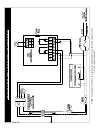
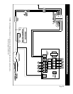
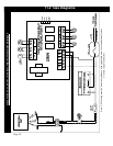
Refer to pages 19 to 23 for oil wiring diagrams and pages 24 to 25 for gas wiring
diagrams.
11. Wiring