


P
USE ONLY THE ULC LISTED BOILER COMPONENTS AND
UL/CSA LISTED OIL OR GAS BURNER COMPONENTS SUPPLIED WITH
THE QHT BIASI B10 SERIES BOILER SYSTEM.
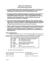
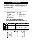
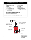
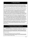
Please refer to figures below for Barometric Damper location for either oil or gas
and to the next page for the proper location of the trim components.
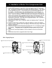
4. Installation of Boiler Trim Components
NOTE: See Page 19 for
available gas burners in
North America
BIAS
Heat Wise
BAROMETRIC DAMPER
WITH MANUAL RESET
SPILL SWITCH
ALTERNATIVE
DAMPER LOCATION
BIASI B10
POWER GAS
BURNER
GAS COCK
DRIP LEG
UNION
GAS TRAIN
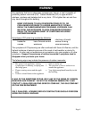
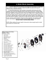
Trim Kit Components
1 - Honeywell L4006A or 7248U
aquastat
1 – Combo pressure/temp gauge
1 – ¾” X 3” Nipple
1 – 30 PSI pressure relief valve
1 – ¾” Boiler drain
1 – Cera-fiber Pad for floor of
combustion chamber
1– ¼” X ½” Bushing
2 – ¾” Plugs
1 – ¾” 90° Elbow
1 – Immersion well
1- Double acting barometric
damper with manual reset spill
switch (Gas systems only)