


Page 16
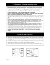
3.Insofar as practical, close all building doors and windows and all doors between
the space in which the appliance remaining connected to the common venting
system is located and other spaces of the building . Turn on any appliance not
connected to the common vent system. Turn on all exhaust fans except for
summer exhaust fans. Close the fireplace damper if applicable.
4.Place in operation the appliance being inspected. Follow the lighting instructions.
Adjust thermostat so appliance will operate continuously.
5.Test for spillage at the barometric damper opening after 5 minutes of main burner
operation. Use the flame of a match or candle, or smoke from a cigarette, cigar or
pipe.
6.After it has been determined that each appliance remaining connected to the
common venting system properly vents when tested as outlined above, return the
doors, windows, exhaust fans, fireplace dampers and any other gas-burning
appliance to their previous condition of use.
7.Any improper operation of the common venting system should be corrected so
the installation conforms with the National fuel Gas Code, ANSI Z223.1 and/or
CAN/CGA B149, Installation Codes. When resizing any portion of the common
venting system, the common venting system should be resized to approach the
minimum size as determined using the appropriate tables in Part 11 of the
National Fuel Gas Code, ANSI Z223.1, and/or CAN/CGA B149, Installation
Codes.
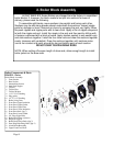
7.1 Common Exhaust Venting Cont.
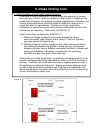
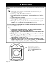
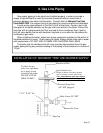
1. Pierce a 5/8” hole into the vent pipe near the appliance outlet. Remove one of the securing
nuts from the pipe of the safety switch. Tighten the other securing nut onto the pipe as far
as possible.
2. Insert the threaded pipe end into the pierced hole, then install the securing nut, then install
the securing nut, which was removed in step 1, and tighten securely.
3. Please consult the wiring section of this manual for the wiring of the blocked flue switch.
7.2 Blocked Flue Switch: