


Page 20
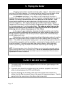
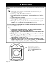
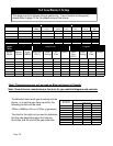
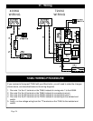
To determine how much gas is coming into the
burner, or to set the gas meter correctly, the
following formula can be used.
The chart to the right can be used to determine
the flow rate depending upon the time per
revolution and the size of the gas meter dial.
Ft
3
/hr = [3600/(sec. Per rev.)]*(Size of gas meter)
Size of Gas Meter Dial
(Cubic Foot)
0.5 1 2
20 90 180 360
25 72 144 288
30 60 120 240
35 51 103 206
40 45 90 180
45 40 80 160
50 36 72 144
55 33 65 131
60 30 60 120
Seconds per
Revolution
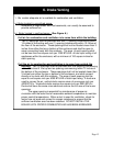
This page is only for boilers using a gas burner. If an oil burner is being used,
please refer to page 18 for the proper setup of the burner.
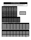
Riello
Natural Gas Propane
Boiler Model Burner Model Input
(MBH)
Man. Pres.
(W.C.)
Head
Setting
Air
Gate
Man. Pres.
(W.C.)
Head
Setting
Air
Gate
B-4 R200 110 1.06” 2.2 1 1.32” 2 1
B-5 R200 140 1.20” 2.8 2 1.76” 2.7 2
B-6 R200 175 1.46” 2.8 3 2.34” 2.9 3
B-7 R400 207 1.22” 2 0 1.48” 2 0
B-8 R400 248 1.26” 2.3 1 1.64” 2.3 1
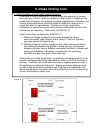
Heat
Wise
Natural Gas
Propane
Boiler
Model
Burner
Model
Input
(MBH)
Man. Pres.
(W.C.)
Head
Setting
Air
Gate
Man.
Pres.
(W.C.)
Head
Setting
Air
Gate
B-4 SU-2A 115 3.5” 12 3 2.3” 12 3
B-5 SU-2A 140 3.2” 15 8.3 1.8” 15 7.75
B-6 SU-2A 175 3.5” 10 13.5 2.3” 10 13.5
B-7 SU-2A 215 3.3” 3 15 2.0” 3 15
B-8 SU-3 272 1.7” 1 3.25 1.3” 1 3.25
B-3 SU-2A 80 3.5” 18 closed 2.0” 22 closed
B-9 SU-3 308 2.3” 1 6.75 1.7” 2 6.5
Orifice
3/16
7/32
9/32
21/64
27/64
No orifice
No orifice
Orifice
3/16
7/32
9/32
21/64
27/64
No orifice
No orifice
8.2 Gas Burner Setup
*Note: These burners may not be used on Biasi equipment in Canada
Note: Consult burner manufacturers literature for gas manifold diagram and controls.