


Page 11
3X 27
2X 4
1
2
22
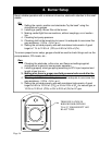
Ø6 Exhaust Breeching
3
3
4
Ø1
1
2
Supply Tapping
Ø
3
4
PRV or Hi Limit Control Tapping
Ø
3
4
Hi Limit Control or PRV Tapping
Ø
3
4
Alternative Boiler Drain Tapping
Ø1
1
2
Return Tapping
Ø
3
4
Boiler Drain Tapping
Ø
1
2
Pressure/Temperature Guage Tapping
Ø
3
4
Alternative Boiler Drain Tapping
Ø3
1
2
Burner Blast Tube Orifice
11
1
2
27
4
1
2
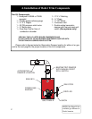
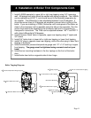
1. Install L4006A aquastat in upper left or right rear tapping using 3/4” immersion
well. All tapings and joints should be sealed with piping compound. The L4006A
can be adjusted up to 220
o
F, and should be set to the desired temperature by
the installer. The differential is also adjustable between 5 and 30 degrees. It
should be set as close to 30 degrees as possible to prevent short cycling of the
boiler. If you are installing a 7248U, Screw the unit to side panel of the boiler as
close to the immersion well as possible using the tabs on the aquastat. Run the
sensor from behind the aquastat to the immersion well and fix it according to
Honeywell’s instructions. The 7248 can be adjusted between 140
o
F and 220
o
F
with a fixed differential of 30 degrees.
2. Install Pressure Relief Valve in opposite, upper rear tapping using 3” nipple and
3/4” elbow
3. Install 3/4” boiler drain in lower left or right rear tapping, or lower front tapping.
4. install 3/4” plug in opposite lower rear tapping, and/or the other plug in lower front
tapping of the boiler.
5. Install combination pressure/temperature gauge and 1/2” x 1/4” bushing in upper
front tapping. The gauge must be tightened using a wrench and not your
hand.
6. Install burner mounting hardware in the four tapings on the front of the boiler
door.
7. Install boiler door bolts on opposite side of door hinge.
4. Installation of Boiler Trim Components Cont.
Boiler Tapping Diagram: