


30
PV500-46U 06/12
b. Attach a manometer to measure the gas pressure at the manual gas shutoff valve located just upstream of
the gas train. Adjust gas train inlet pressure to the specified value (e.g. 14" W.C.), and tightly close the gas
train manual shutoff valve closest to the burner.
c. Reattach the manometer to the gas train manual shutoff valve at the burner and record the measured gas
pressure in inches of water column (W.C.). Measure gas pressure again after 15 minutes. If gas pressure
has increased 0.5" W.C. or more, the gas leak must be isolated to one or more of the operating gas valves.
(For example, a solenoid actuated gas shutoff valve.) After any leaking valve is replaced, the reassembled
gas train must be leak tested again before start-up is attempted.
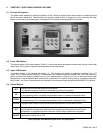
5. Remove enclosure panel cover on the appliance to expose control circuit. A wiring diagram, included in this
packet, will show the controls used in our circuitry.
6. Visually check that all components are intact and no damage has occurred during transit.
7. Check all connections within the control cabinet. A loose connection could cause intermittent shutdowns.
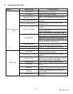
8. All burners will use a hot surface igniter (HSI) as the ignition source. They may use a single gas pressure
regulator and valves, valve regulator combinations or multiple gas trains.
9. Connect a test meter to the control for reading the flame response signal.
NOTE: Some flame controls read the flame signal in micro amps and some in volts DC.
10. CAUTION: Be sure the tank is filled with water. Dry firing can destroy the appliance.
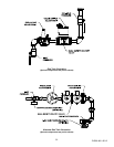
11. Check the inlet gas pressure before start-up, using a manometer or a 0 to 28" W.C. pressure gauge for inlet gas
pressure. (This is the pressure measured before all components in the gas train.) This manometer must stay
connected throughout the testing, as the inlet pressure must be monitored during the firing of the burner.
Record static pressure; it must not exceed 14" W.C. Pressures above this could cause damage to the
diaphragm in the gas valve or pressure regulator.
12. Connect a second manometer to the manifold test port at the shutoff valve closest to the burner.
13. Turn-off main gas shutoff valve.
14. Disable or jumper out any BMS/BAS control interface to allow independent setup and adjustment of
each water heater.
15. Turn unit on using the rocker switch on the front of the control enclosure assembly. When the burner fails to
light, the flame control will lockout.
Start the burner in Low Fire (Burner combustion must be optimized at both Low and High Fire). To set the
TempTrac control for manual modulation output:
Push and hold the EXT key for more than 3 seconds. The
LED switches ON and the PS4 parameter is
displayed in the upper display, while the PAS label is shown in the lower display.
Release the key, and insert the password: 3-2-1. The value of the modulation parameter PS4 will be
displayed in the lower display. (nu) stands for not used. Return to this condition for automatic operation.
To adjust modulation manually, push the SET key, the value starts flashing. Then use UP or DOWN keys to
modify it. 100 = High Fire; 0 = Low Fire.
To exit, press SET + UP or wait 30s without pressing any key.
NOTE: After a modification, it will be possible to enter the Modulation output setting without entering the
password for 10min. After this time you will be asked for the password again.
16. Turn-on main gas shutoff valve.
17. If the operating control switches are closed, the burner blower should come on and pre-purge begins.
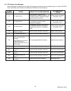
18. If nothing happens, check for a lockout condition and reset it by pushing the flame safeguard reset button.
Some safety devices are wired in the operating circuit and may not indicate alarm. If no indication of alarm
exists, check gas pressure switches, electronic low water cutoffs (if equipped) and temperature limits.