


14
PV500-46U 06/12
7 GAS SUPPLY AND PIPING
Verify that the type of gas specified on rating plate is supplied to the unit. This unit is orificed for operation up to
2000 feet altitude. Appliance Btuh output derates 4% per 1000 feet elevation above sea level. Consult Factory for
installations above 2000 feet elevation.
7.1 Gas Train and Controls Certification
NOTE: The gas train and controls assembly provided on this unit have been tested under the applicable American
National Standard to comply with safety and performance criteria such as proper ignition, combustion and safety
shutdown operation.
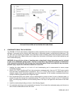
7.2 Gas Control Trains
All models include gas control trains with the following components: main manual shutoff valve, two safety shutoff
valves, proportionator regulator and a final manual valve with the manifold pressure tap on the side of the valve.
These components may be separate or two or more may be combined in a common housing.
Caution: Do not adjust or remove any screws or bolts on gas train control components which are sealed
with a red or blue colored compound. Doing so will void all approvals and warranties.
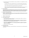
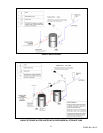
7.3 Inlet Pressure
Measure at the inlet pressure tap located at the main gas cock. The inlet pressure must remain within the minimum
and maximum values while the unit is at rest and while the unit is operating at maximum firing rate.
7.4 Manifold Pressure
Measure at the pressure tap located downstream side of the manual valve closest to the burner. The rated manifold
pressure appears on the product data label located near the front of the appliance.
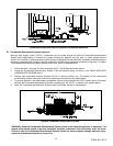
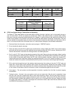
7.5 Gas Piping Size
Use the values in “Convert Fittings To Equivalent Straight Pipe” to add the equivalent straight pipe for each elbow or
tee to obtain the total distance from the meter.
Use this corrected total distance from the meter for determining the suggested pipe size in the “Single Unit
Installation Suggested Gas Pipe Size” table.
*Multiplier for Propane: 1.57
**Multiplier for alternate pressure drops: 0.3" W.C. 0.77; 1.0" W.C. 1.41; 2.0" W.C. 2.00; and 4.0" W.C. 2.82.
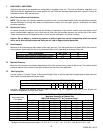
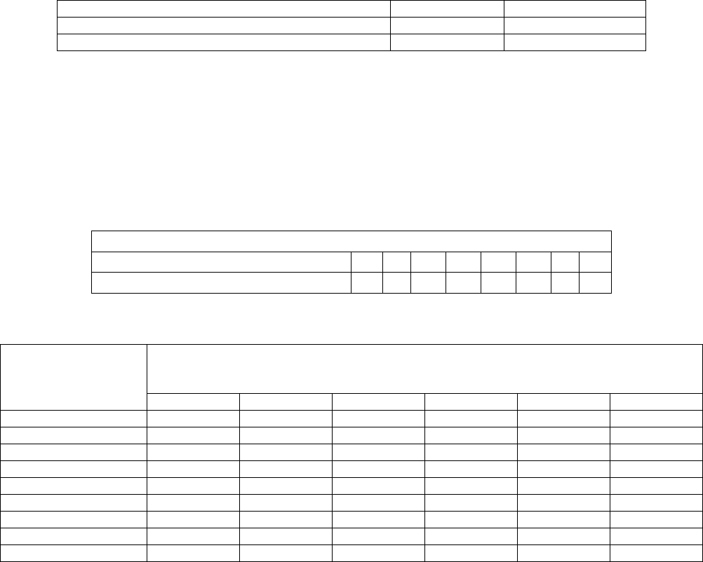
INLET PRESSURE NAT. GAS LP
Maximum Static Pressure (Inches-Water Column) 14" 14"
Minimum Flow Pressure (Inches-Water Column) 4.5" 11"
CONVERT FITTINGS TO EQUIVALENT STRAIGHT PIPE
Diameter Fitting (inches) ¾" 1" 1¼" 1½" 2" 3" 4" 5"
Equivalent Length of Straight Pipe (feet) 2' 2' 3' 4' 5' 10' 14' 20'
Equivalent Feet
From Meter
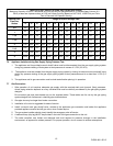
SINGLE UNIT INSTALLATION SUGGESTED PIPE SIZE
Maximum Capacity for Natural Gas*
MBTU/HR Based on 0.5" W.C. Pressure Drop**
1-1/4" 1-1/2" 2" 2½" 3" 4"
25 860 1320 2475 3900 7000 -
40 660 990 1900 3000 5300 -
60 - 810 1520 2400 4300 -
80 - 690 1300 2050 3700 -
100 - 620 1150 1850 3250 6700
125 - - 1020 1650 2950 6000
150 - - 950 1500 2650 5500
175 - - 850 1370 2450 5000
200 - - 800 1280 2280 4600