


15
PV500-46U 06/12
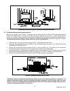
7.6 Appliance Isolation during Gas Supply Piping Pressure Test
1. The appliance and its provided manual shutoff valve must be disconnected from the gas supply piping system
during any pressure testing of that system at test pressures in excess of ½ PSI (3.5 kPa).
2. The appliance must be isolated from the gas supply piping system by closing its individual manual shutoff valve
during any pressure testing of the gas supply piping system at test pressures equal to or less than ½ PSI (3.5
kPa).
3. The appliance and its gas connection must be leak-tested before placing it in operation.
7.7 Gas Connection
1. Safe operation of unit requires adequate gas supply with the required static and dynamic (flow) pressures.
Actual piping selection depends on many variables that must be carefully considered by the gas piping system
designer.
Do not select gas pipe sizes based only on the supplied tables. These tables are for use by the gas piping
system designer as a reference in checking pipe size selections.
2. Gas pipe size may be larger than heater connection.
3. Installation of a union is suggested for ease of service.
4. Install a manual main gas shutoff valve, outside of the appliance gas connection and before the appliance
provided appliance manual shutoff gas valve, when Codes require.
5. The gas system installer should clearly identify the emergency shut-off device.
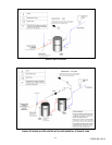
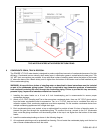
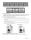
6. A sediment trap (drip leg) MUST be provided in the inlet of the gas connection to the unit.
7. The code compliant vent limiters are designed and must respond to pressure changes in the installation
environment, as opposed to outdoor pressure. For proper operation, do not connect to outdoor atmosphere.
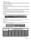
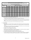
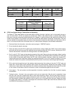
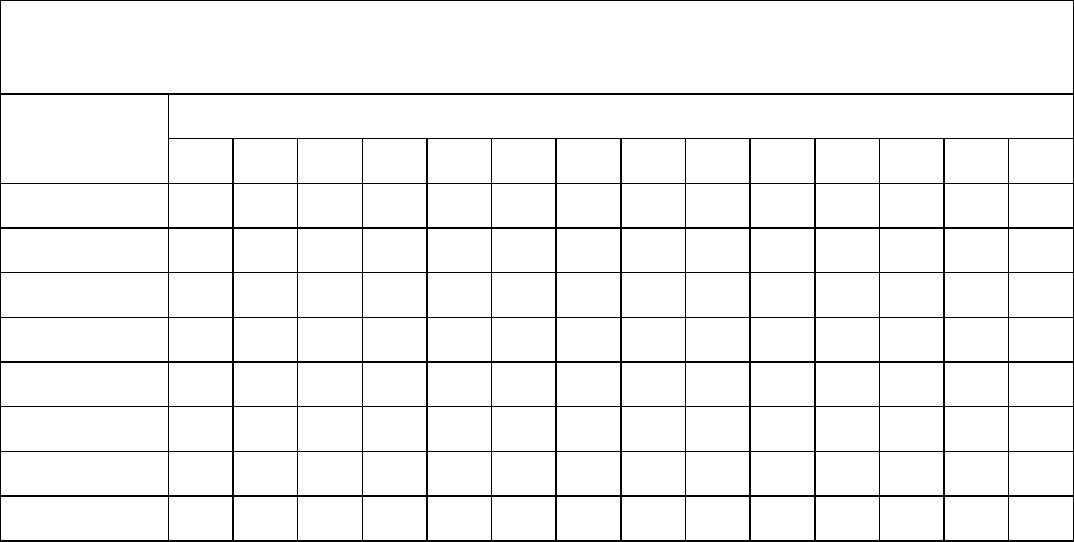
MULTIPLE UNIT INSTALLATIONS GAS PIPING SIZE CHART
Maximum Capacity of Pipe in Thousands of BTU’s per hour for gas pressures of 14 Inches Water Column (0.5
PSIG) or less and a pressure drop of 0.05 Inch Water Column (Based on NAT GAS, 1025BTU’s per Cubic
Foot of Gas and 0.60 Specific Gravity).
Nominal Iron
Pipe Size,
Inches
Length of Pipe in Straight Feet
10 20 30 40 50 60 70 80 90 100 125 150 175 200
3/4
369 256 205 174 155 141 128 121 113 106 95 86 79 74
1
697 477 384 328 292 267 246 256 210 200 179 164 49 138
1 1/4
1400 974 789 677 595 543 502 472 441 410 369 333 308 287
1 1/2
2150 1500 1210 1020 923 830 769 707 666 636 564 513 472 441
2
4100 2820 2260 1950 1720 1560 1440 1330 1250 1180 1100 974 871 820
2 1/2
6460 4460 3610 3100 2720 2460 2310 2100 2000 1900 1700 1540 1400 1300
3
11200 7900 6400 5400 4870 4410 4000 3800 3540 3300 3000 2720 2500 2340
4
23500 16100 13100 11100 10000 9000 8300 7690 7380 6870 6150 5640 5130 4720