


26
PV500-46U 06/12
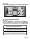
12 REMOTE CONNECTIONS – TERMINAL STRIP
12.1 Making BMS/BAS remote connections for analog and binary (on/off) signals
A terminal strip for the remote connection is located behind the hinged control panel at the top of the cabinet and is
accessed by removing the bottom cover and then removing the screws at the top of the hinged cover.
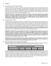
Important: Do not use single strand bell wire for remote field connections to terminals R1-R2 and C1-C2. Use only
multi-strand copper wire. See table below for wire length and gauge:
WARNING: Turn off all electrical service to the appliance when accessing the remote connections located
inside the control cabinet. These terminals are High Voltage. If the electrical service is not turned off and
these terminals are touched, a dangerous shock causing personal injury or loss of life could occur. Close
and fasten the control cabinet cover before restoring electrical service to the appliance.
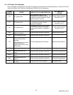
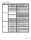
12.2 The Following Describes The Functions Of Each Of These Terminals And The Factory-Installed Options
Required To Activate The Terminals:
Note: Terminal P1-P2 are functional only when the water heater is equipped with the factory installed options
required to activate the terminals. Terminals R1-R2, A1-A2, C1-C2 and T1-T2 are standard pre-wired functions on
all models.
R1-R2: Used to activate / de-activate water heater from remote master control.
Terminals are wired to a relay in a remote Energy Management System. When relay closes, circuit from R1 to R2 is
completed and appliance controls are enabled. Appliance ships from factory with jumper between terminals
Remove jumper when connecting to a remote controller.
A1-A2: Used to activate a remote alarm, signaling shutdown of combustion control.
Provides a maximum 10 amp relay contact closure when the flame safeguard terminates combustion due to a
tripped safety interlock (i.e.: air proving switch, high limit switch, low water flow switch or flame sensor, etc.).
P1-P2: Activates remote equipment and requires confirmation signal back to the appliance.
Provides a maximum 10-amp relay contact closure to activate a remote device (i.e.: mechanical room air louvers,
draft inducer or power vent, etc.). The remote device must send return signal via proving switch to confirming proper
operation to terminals C1-C2, prior to the appliance being able to energize. Options Required - Consult Factory.
C1-C2: Used for proving operation of remote device.
Terminals are wired to a proving switch on a remote device such as a power venter. When relay closes, circuit from
C1 to C2 is completed and appliance controls are enabled. This appliance ships form the factory with jumper
between terminals.
T1-T2: Used for external modulation control.
To connect external modulation control, disconnect and cap the blue wire connected to terminal T2 and connect the
external modulating signal to terminals T1 (positive) and T2 (negative).
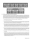
Wire Gauge 18 GA 16GA 14 GA 12 GA
Maximum Length 30 FT 50 FT 75 FT 100 FT