


19
PV500-46U 06/12
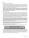
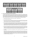
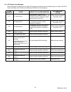
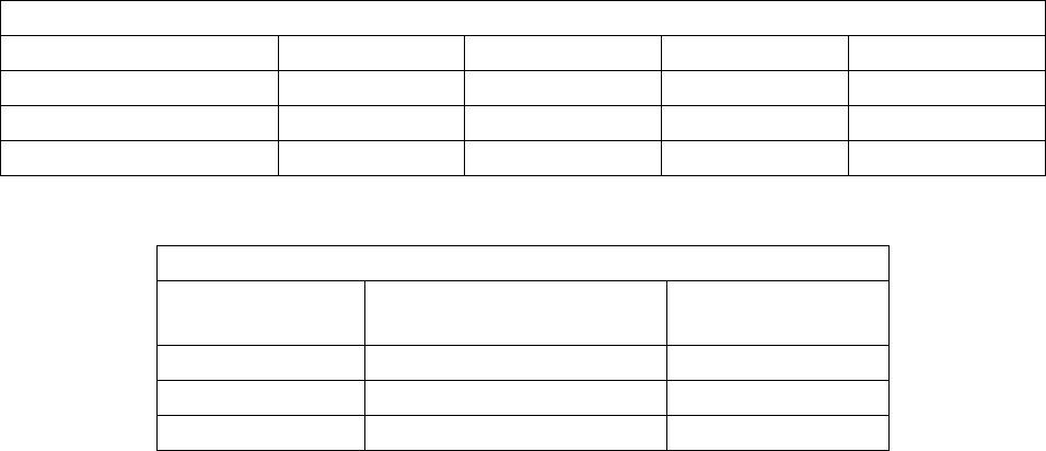
The following vent information is provided for use in design calculations, if needed.
Venting Specifications
Input Mbtu
Products of Combustion
Volume (cfm)
Max Vent
Press. “W.C.
1500 350 1.7
1800 420 2.0
2000 467 2.0
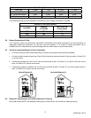
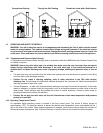
9.4 CPVC Vent System Design, Construction and Assembly:
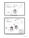
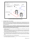
The Power VT Plus water heater can be vented either vertically, through a ceiling or roof, or horizontally through a
wall. The solid CPVC, (CPVC not allowed on models with “SANI” in the model number) or stainless steel venting
listed by a nationally recognized testing laboratory for Category IV positive pressure gas appliance venting can be
routed to the outdoors in any direction, from the flue outlet of the water heater economizer, except down. The vent
must be installed and supported every four feet to slope downward toward the water heater vent connection with at
least ¼ inch drop per linear foot of horizontal vent run, to allow proper drainage of accumulated condensation.
1. Read and follow the information, instructions and warnings in “VENTING” section.
2. Do not insulate the plastic vent pipe.
3. Clean and deburr all solid CPVC (plastic pipe not allowed for venting models with “SANI” in the model number)
pipe ends and the joint area and trial assemble the vent before joining with CPVC cement, following the CPVC
cement manufacturer’s instructions for making sound air and water tight joints.
4. Dry-fit a solid 6” CPVC pipe into the female economizer flue outlet. Remove the pipe and apply a liberal coating
of room temperature vulcanizing (RTV) adhesive to the inside of the stainless steel economizer flue outlet and
to the outside of the plastic pipe. Before the RTV sets, slide the plastic coupling or elbow back into the RTV
coated economizer flue outlet while rotating the pipe approximately 1/8 of a turn. Inspect and apply RTV to the
inside and outside of the plastic to stainless steel joints to provide a continuous water and gas tight assembly.
5. Drill a pilot hole through the top of the stainless steel economizer flue outlet and into the 6” CPVC pipe and
attach with a sheet metal screw (stainless steel screws are recommended). Repeat this step adding a sheet
metal screw to each side of this economizer flue outlet to positively attach the pipe to the flue outlet. Do not drill
or use a screw in the bottom of the flue connector or pipe, as condensate might drip from this point.
6. Vent support – The vent system must be supported at intervals no greater than four feet, to prevent sagging
and distortion.
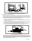
7. Testing for leaks - All joints in the vent system must be air and water tight. After the vent is assembled, close
the end of the vent with a taped plastic bag or some other temporary closure. With the gas supply turned off,
energize the combustion blower to apply air pressure to the vent system. Spray each joint and vent connection
with commercially available leak detection liquid to confirm no air is escaping from any point. Repair any leaks
and retest. After testing is complete, de-energize the combustion blower, wipe clean the leak detection liquid
and REMOVE the temporary vent closure.
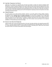
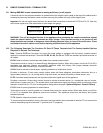
Vent Fitting Equivalent Length
Vent Pipe: 6” Vent 7” Vent 8” Vent 9” Vent
90º Elbow 8 feet 9 feet 10 feet 11 feet
90º Long Radius Elbow 5 feet 5 feet 5 feet 6 feet
45º Elbow 5 feet 5 feet 5 feet 5 feet