


61
Version 04.02.08 Block diagram
PC
BDF - PICO TOP
2 Block diagram
2
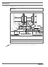
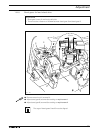
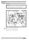
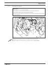
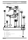
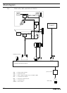
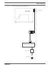
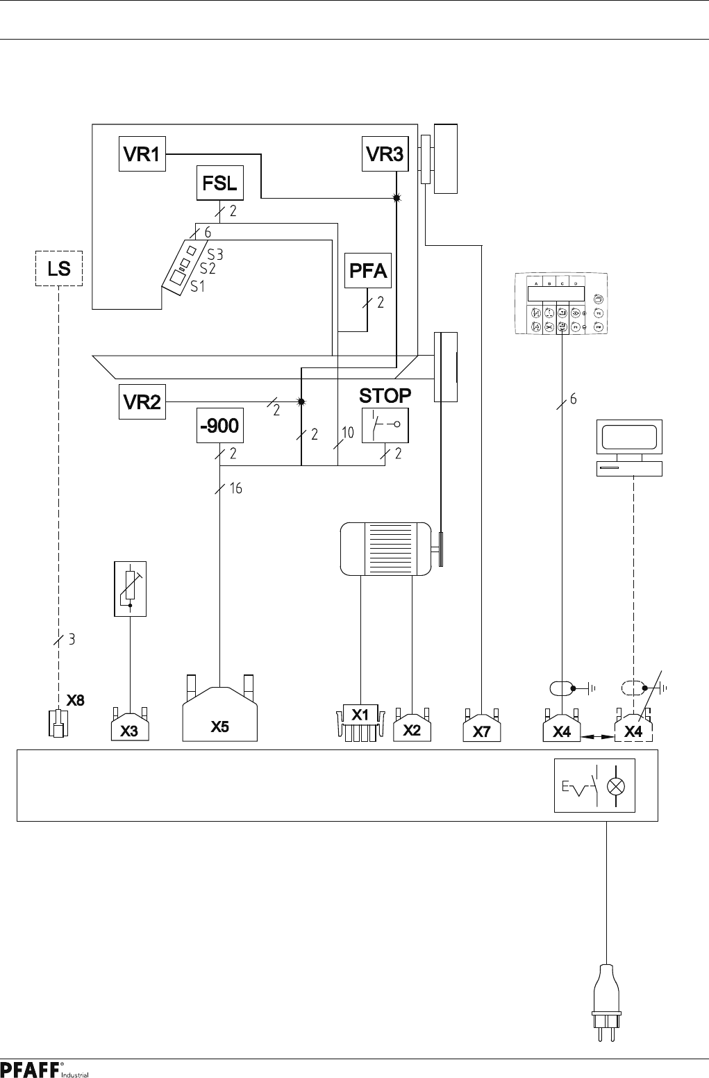
.01 PFAFF 570 / 590 with control unit P44 PD-L
power switch
Control unit P44 PD-L
Control package P44 PD-L
570/590
LS = Light barrier
VR1 = Roller presser release
VR2 = Feed switch-over
VR3 = VR3 – magnet (needle) only on the 571 + 591
FSL = Thread tension release
PFA = Automatic presser foot lift
-900 = Thread trimmer
STOP = Start inhibitor
Drive / Ministop long
incremental transducer
for
software
download
Mains plug
Speedcontrolunit
Synchronizer PD3
only on the 574