


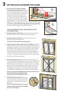
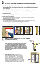
K. Double Doors Only:
Designer Series®: Place a dab of sealant into the center sill strike hole and install the
#8 x 3" at head corrosion resistant screw (provided) or a 3/16" masonry screw into the
hole.
ProLine®: Remove the screw from the sill strike located on the door sill, then place a
dab of sealant into the sill strike hole and install the #8 x 3" at head corrosion resistant
screw (provided) or a 3/16" masonry screw into the hole.
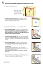
Entry Doors: Remove the two screws from the sill strike
located on the door sill. Place a dab of sealant into the
center sill strike hole and install the #12 x 2-1/2" at head
corrosion resistant screws (provided) or 3/16" masonry
screws into the hole.
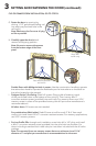
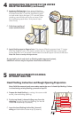
L. Double Doors Only: Shim between the frame and the
rough opening at the head strike location and at every
frame anchor hole location. Keep shims back 1/2" from
interior face of the door frame.
Designer Series: Install the #8 x 3" at head corrosion
resistant screws (provided) into the hole.
ProLine: Remove the screw from the head strike located
on the door head then install the #8 x 3" at head
corrosion resistant screws (provided) into the hole.
Entry Doors: Remove the two screws from the head strike
located on the door head. Install the #12 x 2-1/2" at
head corrosion resistant screws (provided) into the hole.
Note: For doors with pre-drilled installation holes in the
head. If installation holes are present, drill 1/8" diameter
pilot hole into the rough opening and install a #8 x 3"
screw (provided).
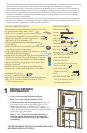
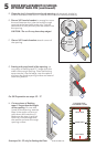
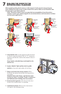
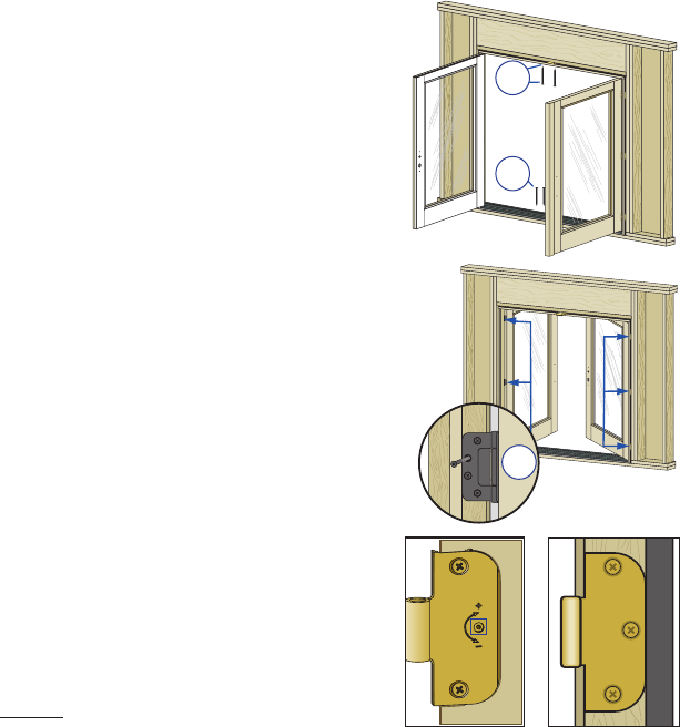
Adjustable
Hinge
Non-Adjustable
Hinge
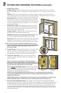
M. On each hinge, starting at the top drill an 1/8" pilot hole
insert a corrosion resistant screw (#8 X 3” provided)
into the open screw hole. Make sure the screw passes
through the shims and into the structural framing.
N. Check door operation. Open and close the door to
check for proper operation. Make sure the door will
latch correctly.
Interior
3L
3K
Interior
3L
3M
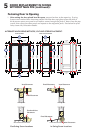
Note: If there are any problems with the operation,
check to confirm the door frame is installed plumb, level
and square. If the reveal between the door panel(s) and
frame is not even, adjustments may be made:
Doors without adjustable hinges: Plastic shims located
behind the hinges may be removed to adjust the reveal
between the door panel and door frame. Additional
hinge shims may be added if required.
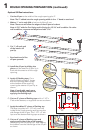
Note: Doors with adjustable hinges will have a (+)(-) on the door panel hinge leaf
to indicate possible adjustments and doors without adjustable hinges do not have
adjustment indicators.
Adjustable hinges are not designed to make up for incorrect installation of a door frame.
Before adjusting hinges, confirm the door is installed plumb, level and square.
O. For Doors with adjustable hinges: The hinges can be used to move the panel side to
side by moving all hinges in the same direction or the hinges can slightly rotate the panel
by adjusting the hinges in opposite directions. Use a T20 Torx wrench for Entry Doors or
a 1/8" Allen wrench for Designer Series doors to turn the center screw clockwise (+) to
increase the space between the hinge side of the frame and door panel. Turn the center
screws counter-clockwise (-) to decrease the space between the hinge side of the frame
and the door panel .
3
SETTING AND FASTENING THE DOOR (continued):