


C3426M-A (5/07) 19
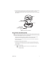
Camera Adjustments
To perform the following camera adjustments, make sure to plug in the camera and service
connectors. You may have to remove the camera module from the back box.
Connect a monitor. Then turn on power to the camera and monitor. To use the service connector, refer
to
Service Connector
on page 30.
To set the DIP switches, or to adjust the auto iris level (DN or CH) or the vertical phase (DW or CW),
you will need a miniature trimpot adjustment tool with a 0.05-inch (1.27 mm) blade. Suggested tools
include a miniature flat-tip screwdriver, a Philmore trimpot tool (#63-8608), and the Philmore 10-piece
tool set (#63-910). To adjust the lens, you may also need a miniature Phillips screwdriver.
After you have adjusted the unit, reinstall the camera module into the back box, and install the trim
ring, bubble, and liner (if necessary).
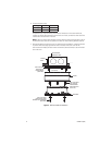
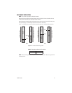
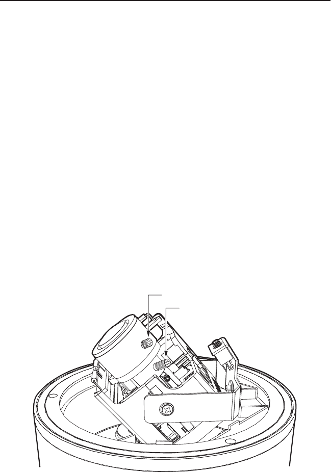
VARIFOCAL LENS ZOOM AND FOCUS ADJUSTMENTS
To adjust the field of view and the focus (refer to Figure 9):
NOTE:
You may need a miniature Phillips or flat-tip screwdriver to loosen and tighten the locking
screws.
1. Loosen the zoom locking screw.
2. Turn the zoom adjustment ring clockwise or counterclockwise to select the field of view.
3. Tighten the zoom locking screw.
4. Loosen the focus locking screw.
5. Turn the focus locking screw clockwise or counterclockwise to adjust the focus.
6. Tighten the focus locking screw.
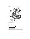
Figure 9.
Location of Zoom and Focus Adjustments
FOCUS
ZOOM