


C3426M-A (5/07) 11
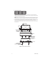
8. Reinstall the back box inside the cover. For vandal-resistant installations, rotate the back box
to position the conduit plug opposite the notch on the side of the cover. Use the two
8-32 x 0.375-inch Phillips pan head screws and washers (removed earlier) to secure the back
box to the cover.
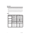
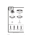
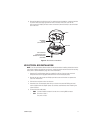
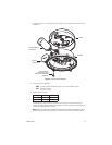
Figure 2.
Basic Surface Installation
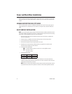
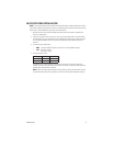
4S ELECTRICAL BOX INSTALLATION
NOTE:
You should install the camera module into the back box before installing the back box into the
cover. When installing the back box into the cover, rotate the camera module to access the mounting
holes (refer to
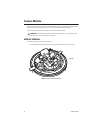
Camera Module
on page 16 for more information).
1. Attach an ICS110-AP adapter plate (not supplied) to a 4S box. Use two 8-32 x 0.75-inch
Phillips flat head screws (supplied with both the IS110 and the adapter plate).
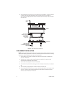
2. Remove the two 8-32 x 0.375-inch Phillips pan head screws and washers to separate the
cover from the back box.
3. Pull the video and power wires into the cover.
4. Attach the cover to the adapter plate with up to four 8-32 x 0.375-inch Phillips pan head
screws (supplied with the adapter plate). Use stainless steel hardware when installing the
system outdoors.
5. Connect the video cable/wires:
•
BNC:
Connect the BNC connector from the unit to a mating BNC connector.
•
UTP:
Blue wire = Video +
Gray wire = Video -
8-32 X 0.375-INCH
PHILLIPS PAN HEAD
SCREWS WITH WASHERS
(SUPPLIED)
MOUNTING
SCREWS
(NOT SUPPLIED)
COVER
BACK BOX