


C3426M-A (5/07) 15
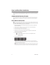
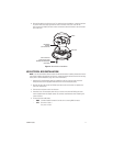
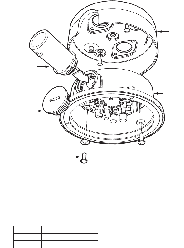
7. Install a 0.75-inch (1.91 cm) threaded conduit connector (not supplied) into the conduit hole in
the back box.
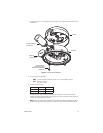
Figure 5.
Side Conduit Installation
8. Connect the video cable/wires:
•
BNC:
Connect the BNC connector from the unit to a mating BNC connector.
•
UTP:
Blue wire = Video +
Gray wire = Video -
9. Connect the power wires.
AC operation only:
If you are wiring more than one Camclosure to the same transformer,
connect one side of the transformer to the red wire on all units; connect the other side of the
transformer to the black wire on all units.
NOTE:
Failure to connect all AC powered units the same way will cause the cameras to be out
of phase with each other and may produce a vertical roll when switching between cameras.
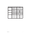
Voltage Red Wire Black Wire
12 VDC + Ground
24 VAC ~ ~
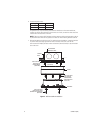
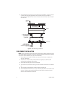
COVER
0.75-INCH CONDUIT
CONNECTOR
REMOVE
CONDUIT PLUG
8-32 X 0.375-INCH
PHILLIPS PAN HEAD
SCREWS WITH WASHERS
(SUPPLIED)
BACK BOX