


8 36ARB2 050505-36
1
/
4"
1"
MAX
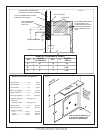
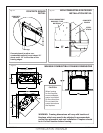
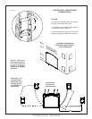
HEARTH EXTENSION
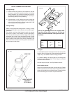
While a hearth extension is not required
for this replace, one is recommended
for aesthetic reasons. The hearth
extension should be noncombustible
and must not be any more than 1"
above the bottom of the replace. If
thicker, replace must be raised up
accordingly.
Caution: Hearth extensions thicker
than 1" will interfere with the window
frame.
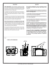
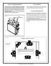
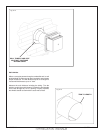
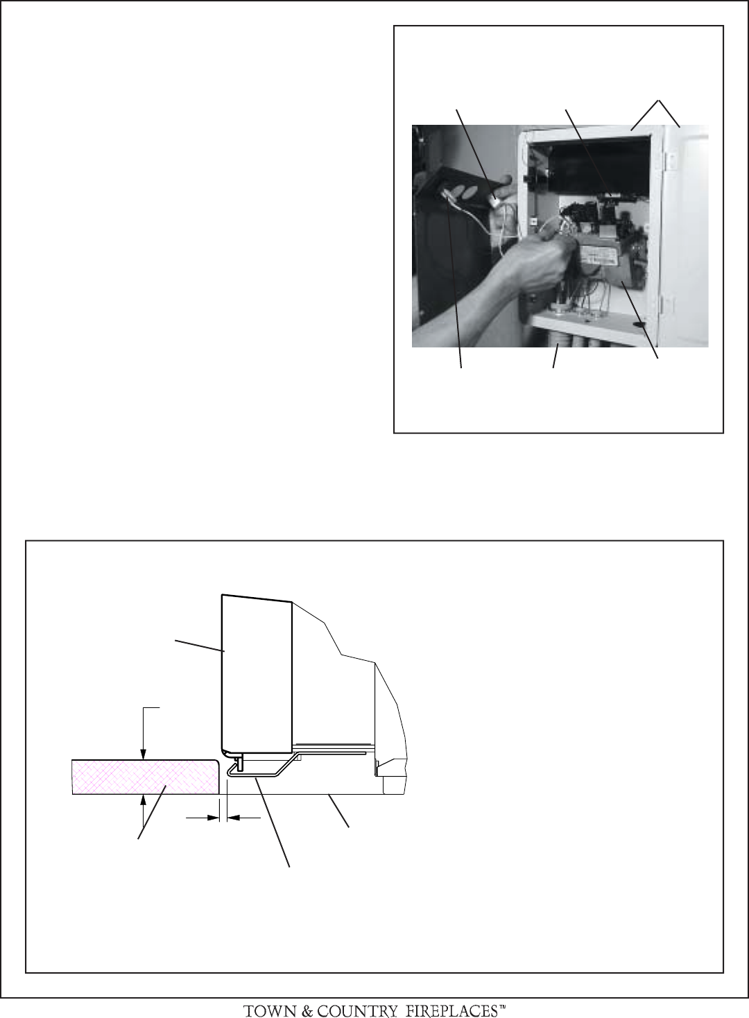
CONTROL BOX
The gas control system is housed in a control box remote of
the replace. Flexible conduits attach the control box to the
replace and house all the plumbing and wiring to the burner.
This unique design allows the control box to be mounted in
a variety of positions on the right or left side of the replace.
The box can be framed into the front right or left face or the
right or left sidewall of the replace enclosure. As the control
system is attached at the factory to exit the right side of the
replace, please see "Control Box Relocation" section to move
the control box to exit the left side.
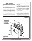
Caution: When positioning the control box, do not over
bend the conduit or use excessive force, as damage may
occur.
1) Remove window frame latch tool and set aside.
2) Remove 4 screws holding control panel in place and
carefully lift off over the control knobs, being sure not to
damage wires and connections to the "Pilot Flame" indi-
cator (millivolt control system only). Carefully disconnect
wires from indicator, and set aside.
3) Attach control box to framing at predetermined depth,
allowing room for wall nishing material. Side brackets
can be adjusted for a trim t.
4) Attach control box to framing at predetermined depth,
allowing room for wall nishing material. Side brackets
can be adjusted for a trim t.
5) Replace door/inner frame assembly and fasten in place.
Note: Gas supply plumbing must be completed and the
spark igniter battery or backup batteries installed before
reinstalling the front control panel.
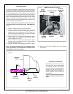
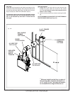
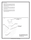
Fig. # 10
PILOT
FLAME
INDICATOR
CONTROL
DOOR AND
FRAME
GAS
VALVE
BURNER
SWITCH
CONDUIT
BATTERY SPARK
IGNITER
MANUAL MILLIVOLT VALVE
6) Reconnect "Pilot Flame" indicator wiring and reinstall
control panel.
WINDOW
FRAME
HEARTH
EXTENSION
WINDOW
TRACK
SUB-
FLOOR
Fig. # 11