


050505-36 36ARB2 17
36"
24"
48"
ADJACENT
24"
(91.5 cm)
(61 cm)
(61 cm)
(122 cm)
STRUCTURES
OR FENCE
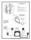
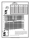
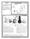
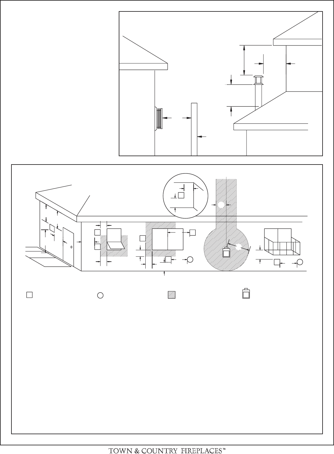
VENT TERMINAL
CLEARANCE
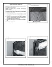
Minimum clearances to the vent terminal
must be maintained as shown in gure #22a
& b. Measure clearances to the nearest
edge of termination hood.
NOTE: Vent terminal must not be
recessed into a wall or siding.
NOTE: LOCAL CODES OR REGULA-
TIONS MAY REQUIRE DIFFERENT
CLEARANCES.
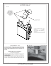
Fig. # 22b
VENT TERMINAL MINIMUM
CLEARANCES
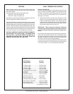
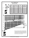
A= clearances above grade, veranda, porch, deck, or balcony
[* 12 inches (30 cm) minimum]
B= clearance to window or door that may be opened [* 12
inches (30 cm) minimum]
C= clearance to permanently closed window [minimum 12
inches (30 cm) recommended to prevent condensation on
window]
D= vertical clearance to ventilated soffi t located above the ter-
minal within a horizontal distance of 2 feet (60 cm) from the
edge of the terminal [30 inches (76 cm) minimum]
E= clearance to unventilated soffi t [30 inches (76 cm) minimum]
F= clearance to outside corner [6 inches (15 cm) minimum]
G= clearance to inside corner [6 inches (15 cm) minimum]
H= * not to be installed above a meter/regulator assembly within
3 feet (90 cm) horizontally from the center-line of the regula-
tor
I= clearance to service regulator vent outlet [* 6 feet (1.8 m)
minimum]
J= clearance to non-mechanical air supply inlet to building or
the combustion air inlet to any other appliance [* 12 inches
(30 cm) minimum]
K= clearance to a mechanical air supply inlet [* 6 feet (1.8 m)
minimum]
L= ^ clearance above paved side-walk or a paved driveway
located on public property [* 7 feet (2.1 m) minimum]
M= clearance under veranda, porch, deck, or balcony [30
inches (76 cm) minimum**]
^ a vent shall not terminate directly above a side-walk or paved driveway which is located between two single family dwellings and
serves both dwellings*
** only permitted if veranda, porch, deck, or balcony is fully open on a minimum of 2 sides beneath the fl oor*
* as specifi ed in CGA B149 Installation Codes, Note: local Codes or Regulation may require different clearances
AIR SUPPLY INLET
VENT TERMINAL GAS METER
FIXED
CLOSED
FIXED
CLOSED
OPEN-
ABLE
OPEN-
ABLE
INSIDE
CORNER
DETAIL
AREA WHERE TERMINAL
IS NOT PERMITTED
M
K
I
A
V
G
G
H
A
J
V
G
A
B
C
A
V
V
A
V
B
F
B
L
V
E
V
V
V
D
Fig. # 22a
VENT TERMINAL MINIMUM
CLEARANCES TO ADJACENT
STRUCTURES