


4
INSTALLATION IN NEW CONSTRUCTION
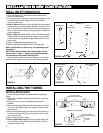
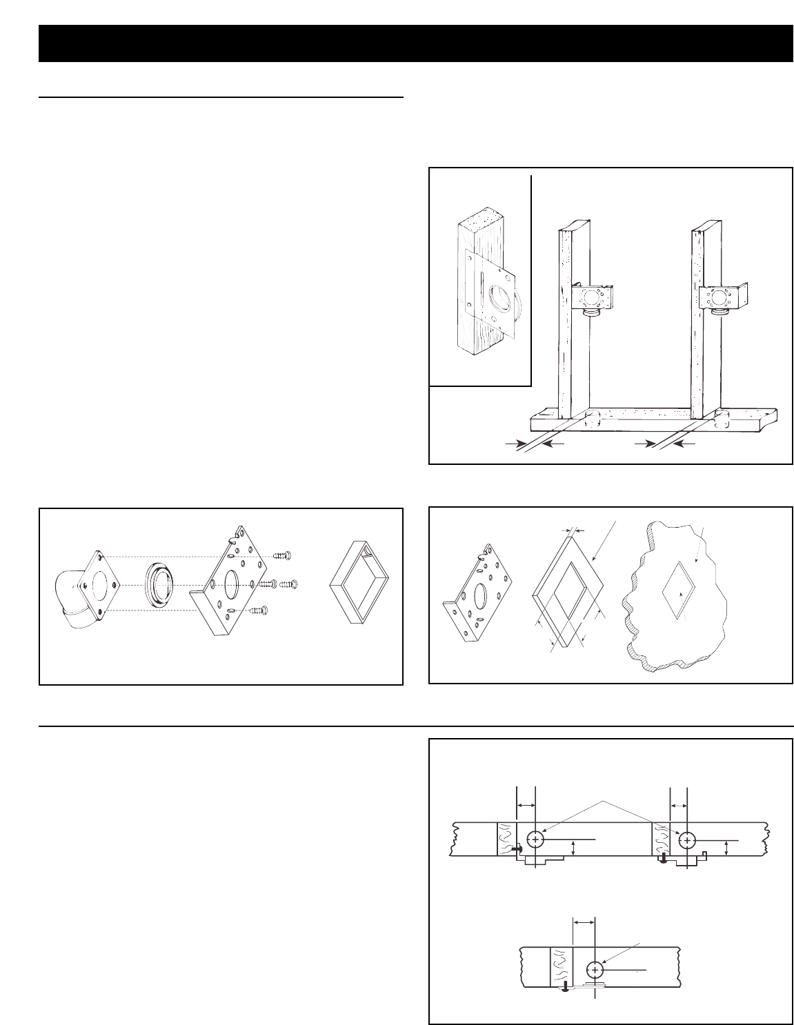
WALL INLET ROUGH-IN
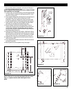
1. Once the locations for wall inlets have been determined,
mount all inlet brackets.
2. To locate bracket on wall stud, measure approximately 18" up
from finished floor level. (Height may vary according to
individual preference.)
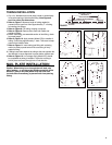
3. Refer to Figure 4. Model 361 for using 360 inlet. Nail bracket
to side of stud so that front edge of bracket is flush to front of
stud. (The bracket may also be nailed to the front edge of the
stud. For front stud mounting, use locating tabs on bracket for
proper alignment.)
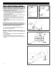
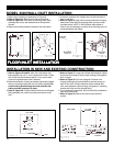
4. Refer to Figure 5. Model 329 for use with 330 inlets. Remove
cardboard from plaster guard frame. Using four (4) provided
screws, attach the appropriate flanged fitting and inlet seal to
back of inlet.
5. Replace cardboard in plaster guard frame.
6. When using Model 329 glue elbow to mounting plate.
NOTE: Configuration of spacer may vary depending upon
installation.
NOTE: When using the Model 361 inlet bracket on walls
thinner than
1
⁄2", use a
1
⁄4" spacer (not furnished) between
the wall and the inlet bracket. See Figure 5A.
Spacer may be made from plywood, masonite, etc. Contact
cement may be used to hold spacer in place during assembly.
MODEL 329
SIDE
MOUNTING
FACE
MOUNTING
MODEL 361
2
3
/8"
1
13
/16"
FIGURE 4
2
1
/4"
3
1
/4"
1
/4"
INLET MOUNTING
BRACKET
SPACER
WALL LESS THAN
1
/2" THICK.
PLASTER
GUARD
HOLE
FIGURE 5
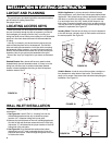
INSTALLATION HINTS
Use the following installation guidelines when installing the
tubing.
1. Start tubing installation at farthest inlet and work toward the
power unit.
2. Tubing run to the power unit should be as straight as
possible.
3. When assembling sections with elbows and tees, make sure
the curve in the fitting is aligned so that the air flows toward
the power unit.
4. Branch lines should always join the trunk line from above or
from the same level. Never join a branch line from an angle
below the trunk line.
5. Secure tubing to joists or studs.
6. Refer to Figure 20 on page 7. Run low voltage wiring and
secure wiring to tubing. Leave approximately 6" of wire for
connection to each inlet.
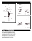
INSTALLING THE TUBING
SIDE
MOUNTING
FACE
MOUNTING
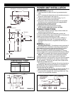
MODEL 361 MOUNTING
2
1
/2" DIA. HOLE
THROUGH SOLE PLATE
2
3
/8"
1
13
/16"
MODEL 329 MOUNTING
2"
FACE
MOUNTING
1
13
/16"
1
13
/16"
2
1
/2" DIA. HOLE
THROUGH SOLE PLATE
1
13
/16"
FIGURE 5A
FIGURE 6
2"-382s
2
5
/
8
-382