


6
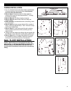
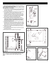
FIGURE 15
FIGURE 16
MODEL 365
DOUBLE FLANGED
TEE
WALL
INLET
MOUNTING
BRACKET
SHORTEN
WALL
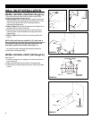
FIGURE 13 FIGURE 14
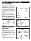
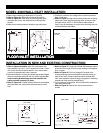
WALL INLET INSTALLATION
MODEL 360 WALL INLET(361 Rough in)
1. Once the walls have been finished, install the wall inlets.
2. Remove the cardboard plaster guard.
3. Refer to Figure 13. For some dry wall or panel construction,
the plaster frame will extend beyond the finished wall. In this
case, remove plaster frame from mounting bracket by
removing mounting screws.
4. Refer to Figure 14. Connect 2-conductor low voltage wire to
terminal screws on back of wall inlet.
5. Guide excess wire back through hole in inlet bracket and
make sure seal is secure between mounting bracket and
flanged fitting.
6. Refer to Figure 15. Place inlet into mounting bracket and
secure.
NOTE: When wall inlets are installed in 1/2" thick walls or
less, the tube of the wall inlet may extend into elbow area of
the flanged fitting and cause blockage. Shorten the wall
inlet tube to prevent this condition. See Figure 16.
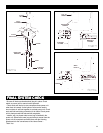
For extra thick walls, use Model 399 extension sleeves to
connect inlet to the flanged fitting.
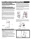
MODEL 330 WALL INLET (329 Rough in)
See Figure 17.
1. Connect 2-conductor low voltage wire to terminal screws on
back of wall inlet.
2. Align inlet mounting holes with holes in mounting plate.
3. Place inlet into mounting plate and secure with two provided
screws.
MOUNTING
PLATE
INLET
FIGURE 17