


8
INSTALLATION IN EXISTING CONSTRUCTION
LAYOUT AND PLANNING
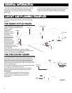
The general layout and planning and the component locations
are the same for existing construction.
See pages 2 and 3.
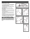
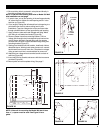
LOCATING ACCESS KEYS
Unless your home is a ranch-style house where a single trunk
line can run directly through the attic or basement, you should
first investigate your house to find the “key” to running your
tubing from level to level. What you're looking for is an accessible
area that is free from obstructions and will accommodate the
2" tubing.
Let's say, for example, you have a two-story house and you
want to locate the power unit in the basement. The first floor
inlets can easily be connected to a trunk line which runs along
the basement ceiling. However, you can't find interior walls on
both the first and second floors which line up and are free from
obstacles. How do you get from the basement to the attic?
Some of the “keys” you might find in your home are illustrated
here.
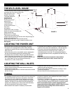
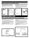
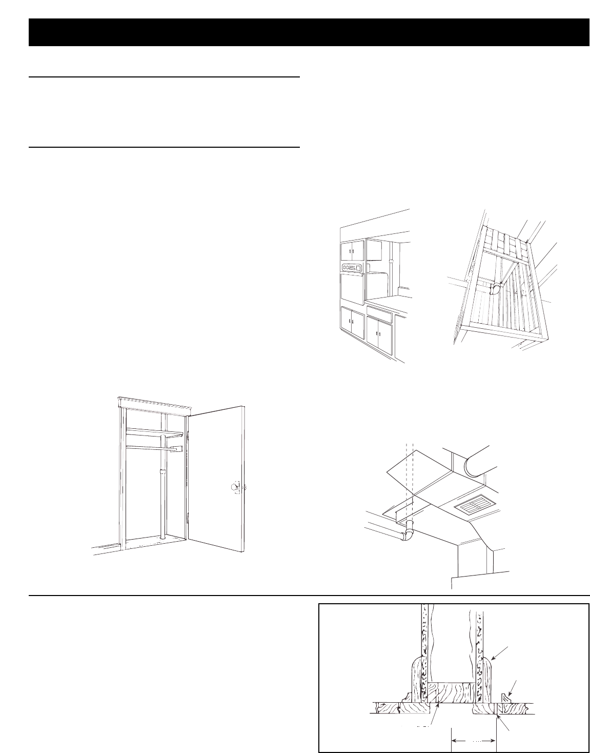
Stacked Closets. Many homes will have an upstairs closet
located directly above a downstairs closet. It is easy to run the
tubing from one floor level to another inside these stacked
closets. In these installations the tubing is often left exposed
inside the closets. See Fi
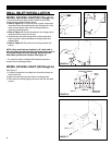
Built-In Appliances. In a home where the kitchen features
built-in appliances, you'll often find a hollow space behind these
appliances. If this space lines up with an obstruction-free interior
wall above or a closet, this might be a “key” to your installation.
In a ranch-style home, this “key” would provide access to run
tubing from a basement located power unit to an attic trunk line.
You may also want to consider running exposed tubing through
cabinets or cupboards. See Figure 22.
Laundry Chute. Pictured here is tubing run from the basement
to the attic through a laundry chute. A dumb-waiter would serve
the same purpose. See Figure 22.
Cold-Air Return. A cold-air return often provides a straight run
from basement to other levels of the house. The ductwork is
easily cut for access. Seal around the tube when completing the
installation. See Figure 23.
FIGURE 21
FIGURE 22
FIGURE 23
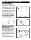
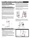
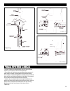
WALL INLET INSTALLATION
Use the following procedures for installation in existing
construction.
1. See Figure 24. A small “Pilot” or “Locating” hole can be
drilled behind baseboard toe strip to determine proper
location of 2
1
⁄2" diameter tubing hole in sole plate.
2. Measure the total thickness of the wall, including baseboard.
One half of this wall thickness measured from the Pilot Hole
(dimension “X”) will determine the proper location of the 21/2"
tubing hole in the sole plate.
3. See Figure 24. Once desired inlet locations have been
determined, cut a 2
1
⁄2" hole in soleplate directly in line with
proposed inlet location. Check through tubing hole to be sure
no obstruction exists.
BASEBOARD
TOE STRIP
PILOT HOLE
“X”
SOLE PLATE
FIGURE 24