


W415-0616 / C / 06.04.08
24
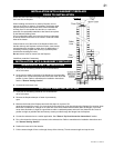
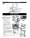
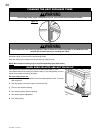
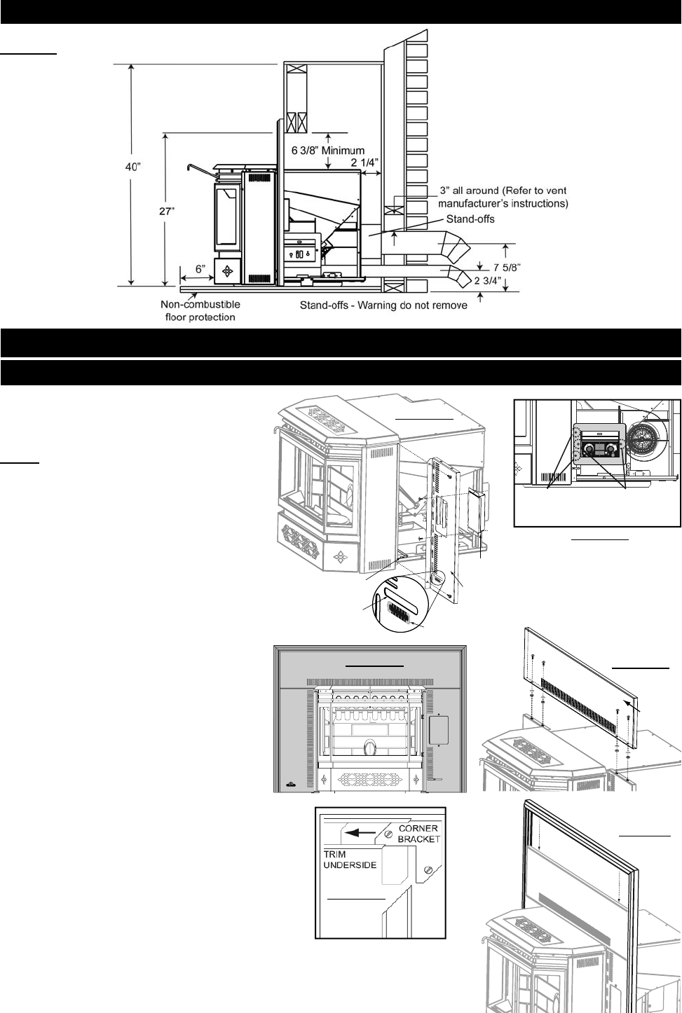
1. Secure the Right Flashing to the
right side of the unit using two of the
#8 x 1/2" screws.
NOTE: Feed the Air Control Rod into the
Air Control Slot on the Right Flashing
before securing. (FIGURE 26)
2. Twist spring handle (supplied with
the heater) onto the air control rod
until it hits the stop.
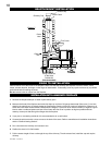
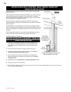
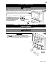
3. Remove the two control panel
securing screws, discard the screws
and shipping bracket. (FIGURE 27)
4. Secure the control panel to the Right
Flashing using the two #8 x 3/8" screws.
(FIGURE 20) Secure the Left Flashing
with the remaining #8 x 1/2" screws.
(FIGURE 26)
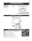
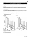
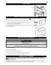
5. Align the holes in the top of the Right and
Left Flashing with those on the bottom lip
of the Top Flashing and secure from the
rear using the four #8-32 x 3/8" screws,
washers and nuts. (FIGURE 29)
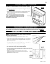
6. The three pieces of trim are assembled in
the same manner as a picture frame. Place the
corner brackets (with screw loosened) into the trim
sections. Tighten the screw spreading the two
pieces apart. Attach the adjoining section. Repeat
with the opposite side. Tighten all screws fi rmly.
(FIGURE 30)
7. Slide the assembled trim down over the fl ashing.
(FIGURE 31)
8. Affi x the logo to the bottom left hand corner of the left fl ashing.
Figure 25
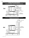
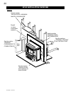
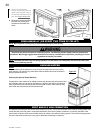
MINIMUM ENCLOSURE CLEARANCES
TRIM
ASSEMBLY
FIGURE 30
FIGURE 31
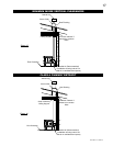
FLASHING INSTALLATION
FIGURE 26
CONTROL
PANEL
AIR
CONTROL
ROD
AIR
CONTROL
SLOT
RIGHT
FLASHING
BURN
RATE LABEL
LO
W
H
I
G
H
1
2
3
4
5
L
O
W
H
I
G
H
1
2
3
4
5
FIGURE 27
PUSH TO START / POUSSEE POUR COMMENCER
5
3
1
2
4
OPTIMUM
1
3
5
4
2
SHIPPING
BRACKET
SECURING
SCREWS
CONTROL
PANEL
SECURING
SCREWS
TOP
FLASHING
FIGURE 29
FIGURE 28
NPI40 FINISHING