


14
W415-0434 / C / 03.24.05
* *
* *
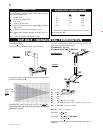
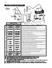
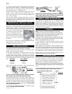
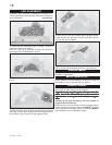
* When using the optional ornamental facia and panels,
the minimum height from the top of the unit to the mantle
is 7".
** A steel stud header is recommended, however tradi-
tional combustible header material may be used.
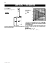
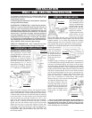
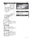
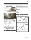
TILES
GD425
BLACK PAINTED FIREPLACE
SURFACE
Tiles must not pro-
trude past the inner
edge of the fireplace
frame to avoid inter-
ference with the
GD425 installation.
Note: In order to avoid the possibility of exposed
insulation or vapour barrier coming in contact with the
fireplace body, it is recommended that the walls of the
fireplace enclosure be “finished” (ie: drywall/
sheetrock), as you would finish any other outside wall
of a home. This will ensure theat clearance to combus-
tibles is maintained within the cavity.
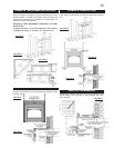
It is not necessary to install a hearth extension, but the
fireplace should be raised up to be flush with either the
hearth or the finished floor.
When roughing in the fireplace, raise the fireplace to ac-
commodate for the thickness of the finished floor materi-
als, i.e. tile, carpeting, hard wood, which if not planned for
will interfere with the opening of the lower access door and
the installation of many decorative flashing accessories.
Objects placed in front of the fireplace should be kept a
minimum of 48" away from the front face.
8. Continue adding rigid venting sections, sealing and
securing as above. Attach a 4" collapsed telescopic pipe to
the last section of rigid piping. Secure with screws and
seal. Repeat using a 7" telescopic pipe.
9. Run a bead of high temperature sealant around the
outside of the 4" elbow. Pull the adjustable pipe a mini-
mum 2" onto the elbow. Secure with 3 screws. Repeat with
the 7" telescopic pipe.
10. In the attic, slide the vent pipe collar down to cover up
the open end of the shield and tighten. This will prevent
any materials, such as insulation, from filling up the 1" air
space around the pipe.
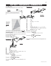
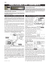
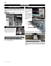
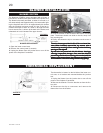
Vertical terminations may display a very active flame. If this
appearance is not desirable, the vent exit must be restricted
using restrictor supplied. This reduces the velocity of the
exhaust gases, slowing down the flame pattern and creat-
ing a more traditional appearance.
1. Remove all obstructing obsta-
cles i.e.: brick panels, logs, etc.
2. Remove the baffle plate from the
rear wall of the firebox, exposing
the two screws from the flue pipe
assembly.
3. Line up the "A" holes on the restrictor plate with the pipe
assembly holes and replace the screws.
4. Replace brick panels, logs, etc.
Purge all gas lines with the glass door of the fire-
place open. Assure that a continuous gas flow is
at the burner before closing the door.
The fireplace is equipped with two 1/4" diameter holes
located in the front left and right corners of the base. For
mobile home installations, the fireplace must be fastened
in place. Use #10 screws, inserted through the holes in
the base to secure. It is recommended that the fireplace
be secured in all installations.
FIGURE 27
FIGURE 26
GAS INSTALLATION
MOBILE HOME INSTALLATION
FRAMING
RESTRICTING VERTICAL VENTS
Non-combustible material (brick, stone or ceramic tile) may
protrude over the black painted surface of the fireplace
front and is required for use in conjunction with the GD425
kit. This kit is designed to accommodate a noncombus-
tible material to a maximum finished thickness of
3
/
4
".
PROTRUDING FINISH
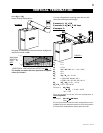
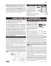
Proceed once the vent installation is complete.
1. Route a 3/8" N.P.T. black iron gas line, 1/2" type-L copper
tubing or equivalent to the fireplace.
2. For ease of accessibility, an optional remote wall switch
or millivolt thermostat may be installed in a convenient
location. Route 2 strand (solid core) millivolt wire through
the electrical hole located at the bottom left side of the unit.
The recommended maximum lead length depends on wire
size: WIRE SIZE MAX. LENGTH
14 gauge 100 feet
16 gauge 60 feet
18 gauge 40 feet
Attach the two leads to terminals 1 and 3 located on the
gas valve.
Do not connect either the wall switch, thermo-
stat or gas valve to electricity (110 volts).
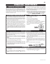
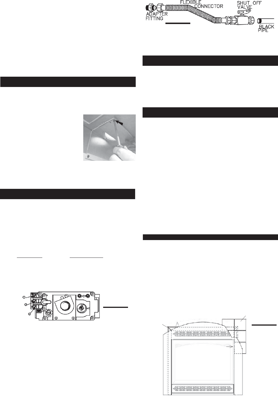
3. Install rigid black pipe, 1/2" type-L copper tubing or, if
local codes permit, a 3/8" flex connector and shutoff valve
to the gas line and the fireplace gas valve. Seal and tighten
securely. An adaptor fitting is required between the gas
valve and the copper tubing or flex connector. DO NOT KINK
THE FLEXIBLE CONNECTOR.
4. Check for gas leaks by brushing on a soap and water
solution. DO NOT USE OPEN FLAME.
FIGURE 33
HOLE "A"