


13
W415-0434 / C / 03.24.05
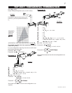
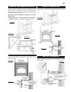
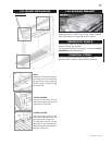
FIGURE 23
1. Move the fireplace into position.
2. Fasten the roof support to the
roof using the screws provided.
FIGURE 16. The roof support is
optional. In this case the venting
is to be adequately supported
using either an alternate method
suitable to the authority having ju-
risdiction or the optional roof sup-
port.
3. Apply high temperature seal-
ant to the outer edge of the inner
sleeve of the air terminal. Slip a
4" diameter coupler a minimum
of 2" over the sleeve and secure using 3 screws.
4. Apply high temperature sealant to the outer edge of the of
the outside sleeve of the air terminal. Slip a 7" diameter
coupler over the sleeve and secure as before. FIGURE 19.
Trim the 7" coupler even with the 4" coupler end.
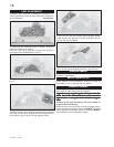
5. Thread the air terminal pipe assembly down through the
roof support and attach, ensuring that a minimum 16" of
air terminal will penetrate the roof when fastened.
FIGURE 18. If the attic space is tight, we recommend
threading the Wolf Steel vent pipe collar or equivalent
loosely onto the air terminal assembly as it is passed
through the attic. The air terminal must be located verti-
cally and plumb.
6. Remove nails from the shingles, above and to the sides
of the chimney. Place the flashing over the air terminal and
slide it underneath the sides and upper edge of the
shingles. Ensure that the air terminal is properly centered
within the flashing, giving a 3/4" margin all around. Fasten
to the roof. Do NOT nail through the lower portion of the
flashing. Make weather-tight by sealing with caulking. Where
possible, cover the sides and top edges of the flashing
with roofing material.
7. Apply a heavy bead of waterproof caulking 2 inches above
the flashing. Slide the storm collar around the air terminal
and down to the caulking. Tighten to ensure that a weather-
tight seal between the air terminal and the collar is achieved.
Attach the other storm collar centered between the air in-
take and air exhaust slots onto the air terminal. Tighten
securely. Attach the rain cap.
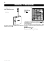
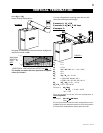
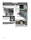
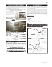
FIGURE 24
1. Install the 4 inch diam-
eter aluminum flexible
liner to the fireplace. Se-
cure with 3 screws and flat
washers. Seal the joint
and screw holes using
the high temperature seal-
ant Mill Pac.
2. Install the 7 inch diameter alu-
minum flexible liner to the fireplace.
Attach and seal the joints.
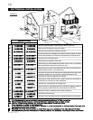
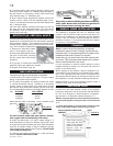
For optimum performance it is recommended that all
horizontal runs have a ¼ inch rise per foot.
For safe and proper operation of the fireplace, follow
the venting instructions exactly.
The vent system must be supported approximately every 3
feet for both vertical and horizontal runs. Use Napoleon
vent spacers W615-0033 every 3 feet and on either side of
each elbow to maintain the minimum 1¼" clearance be-
tween the outer and inner vent pipes. Use Napoleon sup-
port ring assembly W010-0370 or equivalent noncombus-
tible strapping to maintain the minimum 1" clearance to
combustibles for both vertical and horizontal runs.
All inner exhaust and outer intake vent pipe joists may
be sealed using either Red RTV high temp silicone seal-
ant or Black high temp Mill Pac with the exception of the
fireplace exhaust flue collar which must be sealed us-
ing Mill Pac (not supplied).
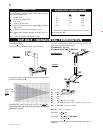
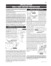
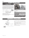
1. Move the fireplace into position. Measure the vent length
required between terminal and fireplace taking into account
the additional length needed for the finished wall surface
and any 1¼" overlaps between venting components.
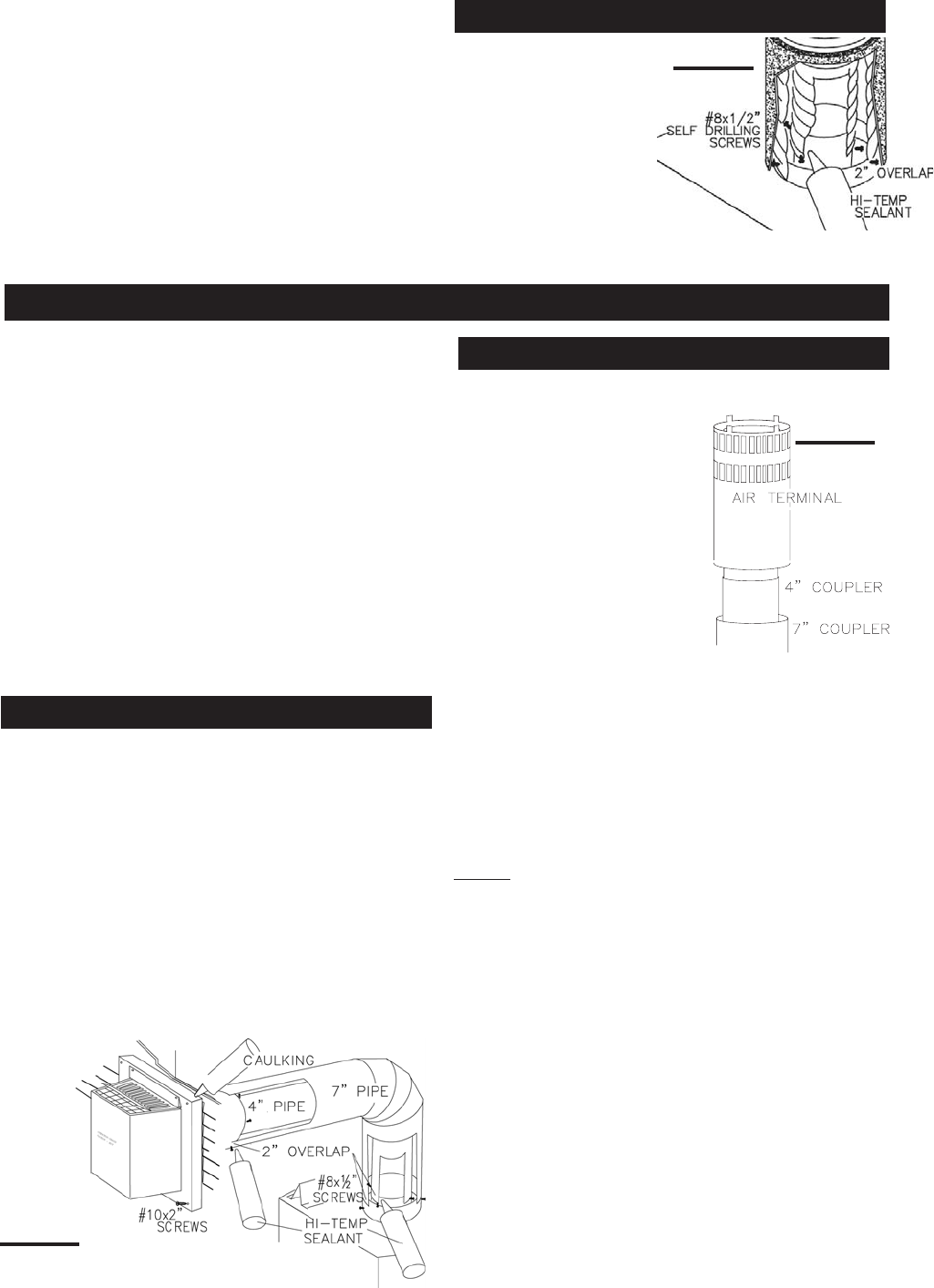
2. Apply high temperature sealant Mill Pac to the outer edge
of the 4" inner collar of the fireplace. Attach the first vent
component and secure using 3 self tapping screws. Re-
peat using 7" piping.
3. Holding the air terminal (lettering in an upright, readable
position), insert into both vent pipes with a twisting motion
to ensure that both the terminal sleeves engage into the
vent pipes and the sealant. Secure the terminal to the exte-
rior wall and make weather tight by sealing with caulking
(not supplied). The air terminal may be recessed into the
exterior wall or siding by 1½", the depth of the return
flange.
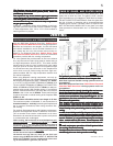
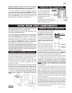
FIREPLACE VENT CONNECTION
USING RIGID VENT COMPONENTS
HORIZONTAL AIR TERMINAL INSTALLATION
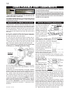
VERTICAL VENTING INSTALLATION
FIGURE 25
Spacers are attached to the 4" inner flex liner at prede-
termined intervals to maintain a 1-1/4" air gap to the 7"
outer liner. These spacers must not be removed.
7. If more liner needs to be used to reach the fireplace,
couple them together as illustrated in FIGURE 13. The vent
system must be supported approximately every 3 feet for
both vertical and horizontal runs. Use Wolf Steel support ring
assembly W010-0370 or equivalent noncombustible strap-
ping to maintain a clearance to combustibles of 1".