11
W415-0434 / C / 03.24.05
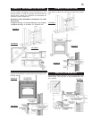
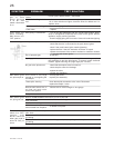
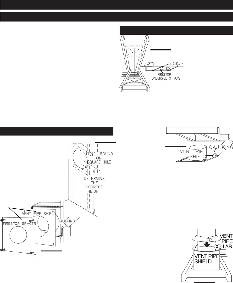
FIGURE 14
OR
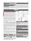
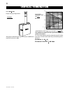
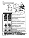
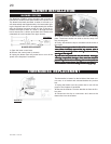
This application occurs
when venting through a
roof. Installation kits for
various roof pitches are
available from your Na-
poleon dealer. See Ac-
cessories to order the
specific kit required.
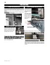
1. Determine the air ter-
minal location, cut and
frame 9½ inch open-
ings in the ceiling and the roof to provide the minimum
clearance between the fireplace pipe / liner and any com-
bustible material. Try to center the exhaust pipe location
midway between two joist to prevent having to cut them.
Use a plumb bob to line up the center of the openings.
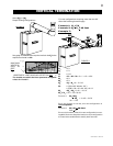
DO NOT FILL THIS SPACE WITH ANY TYPE OF MATERIAL.
A vent pipe shield will
prevent any materials
such as insulation,
from filling up the 1"
air space around the
pipe. Nail headers be-
tween the joist for ex-
tra support.
2. Apply a bead of caulking (not supplied) to the framework
or to the Wolf Steel vent pipe shield plate or equivalent (in
the case of a finished ceiling), and secure over the open-
ing in the ceiling. A firestop must be placed on the bottom
of each framed opening in a roof or ceiling that the venting
system passes through. Apply a bead of caulking all around
and place a firestop spacer over the vent shield to restrict
cold air from being drawn into the room or around the fire-
place. Ensure that both spacer and shield maintain the
required clearance to combustibles. Once the vent
pipe / liner is installed in its final position, apply sealant
between the pipe / liner and the firestop spacer.
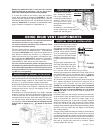
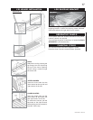
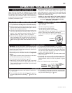
3. In the attic, after the pipe / liner
has been installed, slide the
vent pipe collar down to cover up
the open end of the shield and
tighten. This will prevent any ma-
terials, such as insulation, from
filling up the 1" air space around
the pipe.
*
The 11½ inch framing dimension may be reduced to a
9½ inch opening if the vent length, from the fireplace to
the framed hole, is 24 inches or greater. If not, it is rec-
ommended to use a terminal extension plate, W500-0103,
when mounting the air terminal.
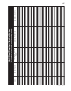
FIGURE 13
*
INSTALLATION
WALL AND CEILING PROTECTION
HORIZONTAL INSTALLATION
VERTICAL INSTALLATION
FIGURE 17
FIGURE 16
FIGURE 15
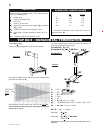
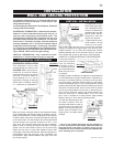
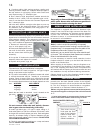
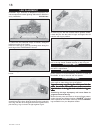
For optimum performance it is recommended that all
horizontal runs have a minimum ¼ inch rise per foot
using flexible venting.
For safe and proper operation of the fireplace, follow the
venting instructions exactly.
HORIZONTAL TERMINATION: A clearance to combus-
tibles of 2" must be maintained during the first 24" of
venting when penetrating combustible walls. The
firestop spacer (GD-500.106 ) supplied with the unit
should be used to maintain this clearance. The first two
feet of outer 7" diameter vent pipe, from the appliance
must be wrapped in the 1 inch thick insulation sleeve
(supplied) as well as having a 1 inch air gap. Thereafter
a 1" clearance to combustibles may be maintained us-
ing firestop spacer (GD-500.96 for use with flexible vent-
ing or GD-500.136 for use with rigid venting).
VERTICAL TERMINATION: Only a clearance to com-
bustibles of 1" all around the vent pipe is required.
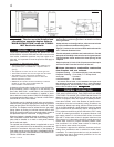
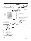
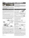
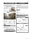
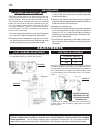
HORIZONTAL INSTALLATION:
This application occurs when
venting through an exterior wall.
FIGURES 2a-d. Having deter-
mined the air terminal location,
cut and frame a hole in an exterior
wall with a minimum square or
round opening of 11½"*. (As an
alternative to framing, a vent pipe
shield may be installed, ensuring
a 1" clearance to combustibles.
Mark and cut the vent pipe shield to the determined depth
of the combustible wall. Apply a bead of caulking (not sup-
plied) to the framework or to the shield plate (in the case of
a finished wall) and secure the shield through the opening
to the interior wall. The final location of the vent pipe shield
should maintain the required clearance to the 7" vent
pipe / liner. Do not fill this cavity with any type of material.
Apply a bead of caulking all around and place a firestop
spacer over the vent shield to restrict cold air from being
drawn into the room or around the fireplace. Ensure that
both spacer and shield maintain the required clearance to
combustibles. Once the vent pipe / liner is installed in its
final position, apply sealant between the pipe / liner and
the firestop spacer.