


10
W415-0614 / A / 07.24.07
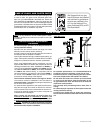
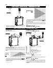
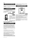
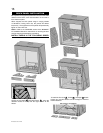
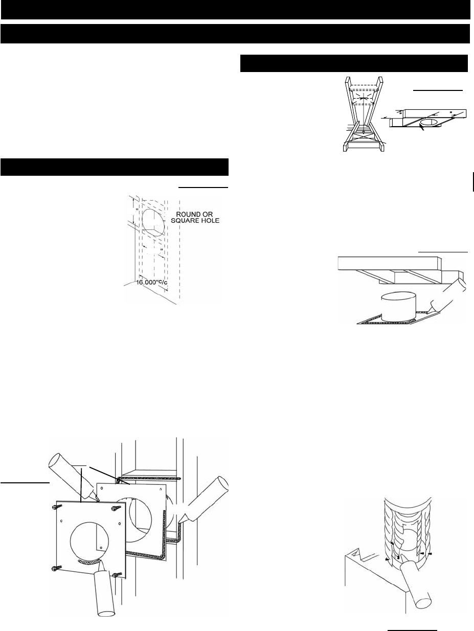
This application occurs when venting
through an exterior wall. Having
determined the air terminal loca-
tion, cut and frame a hole in an
exterior wall. The recommended
framed opening is 14
1
/2” W x
14
1
/2” H with a minimum 14
1
/2”
round or square opening inside
a fi nished wall.
See fi gure15.
1. Mark and cut the vent pipe
shield to the determined depth
of the combustible wall. Apply
a bead of caulking (not supplied) to the framework or to
the shield plate (in the case of a fi nished wall) and secure
the shield through the opening to the interior wall. The fi nal
location of the vent pipe shield should maintain the required
clearance to the 10” vent pipe / liner. (See note above). Do
not fi ll this cavity with any type of material. Apply a bead of
caulking around the fi restop spacer then along the edge of the
vent shield to restrict cold air from being drawn into the room
or around the fi replace. Ensure that both spacer and shield
maintain the required clearance to combustibles. Once the
vent pipe / liner is installed in its fi nal position, apply sealant
between the pipe / liner and the fi restop spacer.
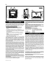
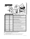
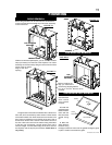
This application occurs
when venting through a
roof. Installation kits for
various roof pitches are
available from your NA-
POLEON® dealer. See
Accessories to order the
specifi c kit required.
1. Determine the air terminal location, cut and frame
14
1
/2” W x 14
1
/2” H openings in the ceiling and the roof to
provide the minimum 2 inch clearance between the fi replace
pipe / liner and any combustible material. Try to centre the
exhaust pipe location midway between two joist to prevent
having to cut them. Use a plumb bob to line up the centre of
the openings. DO NOT FILL THIS SPACE WITH ANY TYPE
OF MATERIAL.
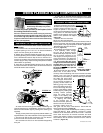
A vent pipe shield will
prevent any materials
such as insulation, from
fi lling up the 1” air space
around the pipe. Nail
headers between the
joist for extra support.
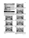
2. Apply a bead of caulking (not supplied) to the framework
or to the Wolf Steel vent pipe shield plate or equivalent (in the
case of a fi nished ceiling), and secure over the opening in the
ceiling. A fi restop must be placed on the bottom of each framed
opening in a roof or ceiling that the venting system passes
through. Apply a bead of caulking all around and place a fi re-
stop spacer over the vent shield to restrict cold air from being
drawn into the room or around the fi replace. Ensure that both
spacer and shield maintain the required clearance to combus-
tibles. Once the vent pipe / liner is installed in its fi nal position,
apply sealant between the pipe / liner and the fi restop spacer.
3. In the attic, after the pipe / liner has been installed, slide
the vent pipe collar down to cover up the open end of the
shield and tighten. This will prevent any materials, such as
insulation, from fi lling up the 1” air space around the pipe.
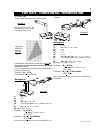
VENT PIPE SHIELD
FIRESTOP SPACER
CAULKING
FIGURE 13
FIGURE 14
OR
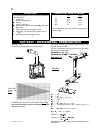
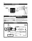
HORIZONTAL INSTALLATION
VERTICAL INSTALLATION
FIGURE 15
INSTALLATION
WALL AND CEILING PROTECTION
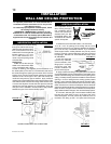
For optimum performance it is recommended that all
horizontal runs have a minimum of 1/4” rise per foot
using fl exible venting.
For safe and proper operation of the fi replace, follow
the venting instructions exactly.
HORIZONTAL TERMINATION: A clearance to com-
bustibles of 2” must be maintained when penetrating
combustible walls. The fi restop spacer (W615-0075)
supplied with the unit should be used to maintain this
clearance.
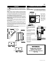
SHOWN FROM INSIDE THE STRUCTURE
CAULKING
VENT PIPE
SHIELD
FIGURE 16
FIRESTOP
UNDERSIDE OF JOIST
14
1
/2
14
1
/2
14
1
/2
14
1
/2
14
1
/2
Hi-Temp
Sealant
2” Overlap
#8x1/2”
Self Drilling
Screws
FIGURE 17