


6
W415-0580 / C / 04.07.08
*
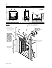
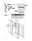
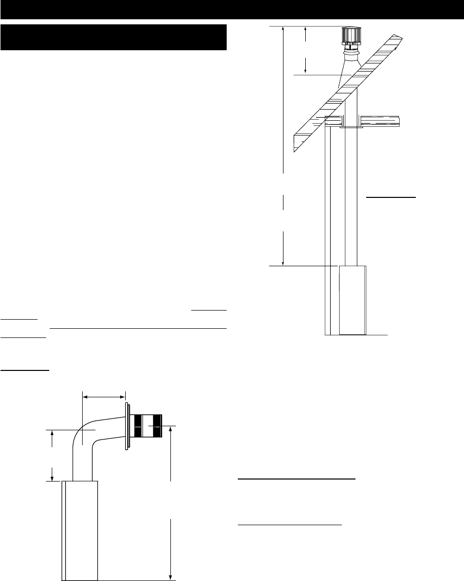
16”
MINIMUM
40 FEET
MAXIMUM
3 FEET
MINIMUM
FIGURE 3b
When using Wolf Steel Ltd.venting components, use only approved
Wolf Steel Ltd. fl exible vent components with the following termina-
tion kits: WALL TERMINAL KIT GD622, or 1/12 TO 7/12 PITCH
ROOF TERMINAL KIT GD610, 8/12 TO 12/12 ROOF TERMINAL KIT
GD611, FLAT ROOF TERMINAL KIT GD612. With fl exible venting, in
conjunction with the various terminations, use either the 5 foot vent
kit GD620 or the 10 foot vent kit GD630. These vent kits allow for
either horizontal or vertical venting of the fi replace.
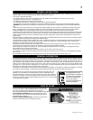
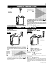
The maximum allowable vertical vent length is 40 feet. The
maximum number of allowable 8” vent connections is three hori-
zontally or vertically (excluding the fi replace and the air terminal
connections).
For optimum fl ame appearance and fi replace performance, keep the
vent length and number of elbows to a minimum. The air terminal must
remain unobstructed at all times. Examine the air terminal at least
once a year to verify that it is unobstructed and undamaged.
When venting, the horizontal run must be kept to a maximum
of 20 feet. If a 20 foot horizontal run is required, the fireplace
must have a minimum vertical rise immediately off the fire-
place of 57“. When terminating vertically, the vertical rise is
a minimum 3 feet and a maximum 40 feet above the fireplace.
FIGURES 3a-b.
VENTING
VENTING LENGTHS AND AIR TERMINAL
LOCATIONS
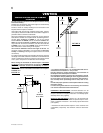
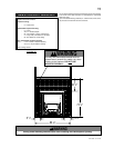
* For optimum performance, it is recommended that all hori-
zontal runs have a minimum ¼“ rise per foot.
Provide a means for visually checking the vent connection to
the fireplace after the fireplace is installed.
Do not allow the inside liner to bunch up on horizontal or vertical
runs and elbows. Keep it pulled tight. A 3/4” air gap between the
inner and outer liner all around is required for safe operation.
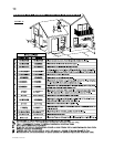
Use a firestop when penetrating interior walls, floor or ceil-
ing.
For safe and proper operation of the fireplace follow the venting
instruction exactly.
If vertical rises greater than 57“ are necessary, the increased
rise must be deducted from the horizontal run.
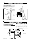
HORIZONTAL VENT SECTIONS: A minimum clearance of 2” all
around the vent pipe on all horizontal runs to combustibles is required
except for clearances in fi replace enclosures**. Use fi restop spacer
assembly W010-1797 (supplied).
VERTICAL VENT SECTIONS: A minimum of 1” all around the vent
pipe on all vertical runs to combustibles is required except for clear-
ances in fi replace enclosures**. Use fi restop spacer W615-0075
(not supplied).
** Horizontal and vertical sections require 5” and 9” clearance from
combustibles, respectively. See minimum enclosure clearances
section.
For safe and proper operation of the fi replace follow the venting
instructions exactly.
Deviation from the minimum vertical vent length can create diffi culty
in burner start-up and/or carboning.
Provide a means for visually checking the vent connection to the
fi replace after the fi replace is installed.
Vent lengths that pass through unheated spaces (attics, garages,
crawl spaces) should be insulated with the insulation wrapped in a
protective sleeve to minimize condensation.
71
3
/4”
MINIMUM
PLUS RISE*
24” MAXIMUM
13
1
/2”
MINIMUM
FIGURE 3a