


24
W415-0580 / C / 04.07.08
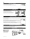
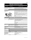
LOW BATTERY / MANUAL BYPASS
The life span of the remote batteries depends on various factors: quality of the batteries, the number of ignitions, the number of changes to
the room thermostat set point, etc.
When the transmitter batteries are low, a Battery Icon will appear on the LCD display before all battery power is lost. When the batteries are
replaced this Icon will disappear.
When the receiver batteries are low, no “beep” will be emitted from the receiver when it receives an ON/
OFF command. This is an alert for the receiver that there’s low battery. When the batteries are replaced the
“beep” will be emitted from the receiver when the ON/OFF Key is pressed.
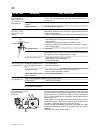
If the batteries of the receiver or transmitter are low, the appliance can be turned on manually by sliding the
three position slider switch on the receiver to the “ON” position. This will bypass the remote control feature
and the appliance main burner will come on if the gas valve is in the “ON” position.
FIGURE 63
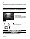
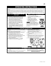
Refer to fi replace operation when communications between receiver and transmitter have been lost.
The receiver is equipped with batteries which enable the on/off or thermostat function to control the fi replace during a power failure. The
blower and night light™ features will not operate during a power failure.
The receiver will emit a “beep” sound to confi rm programming has been successful once power is restored.
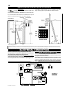
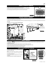
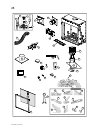
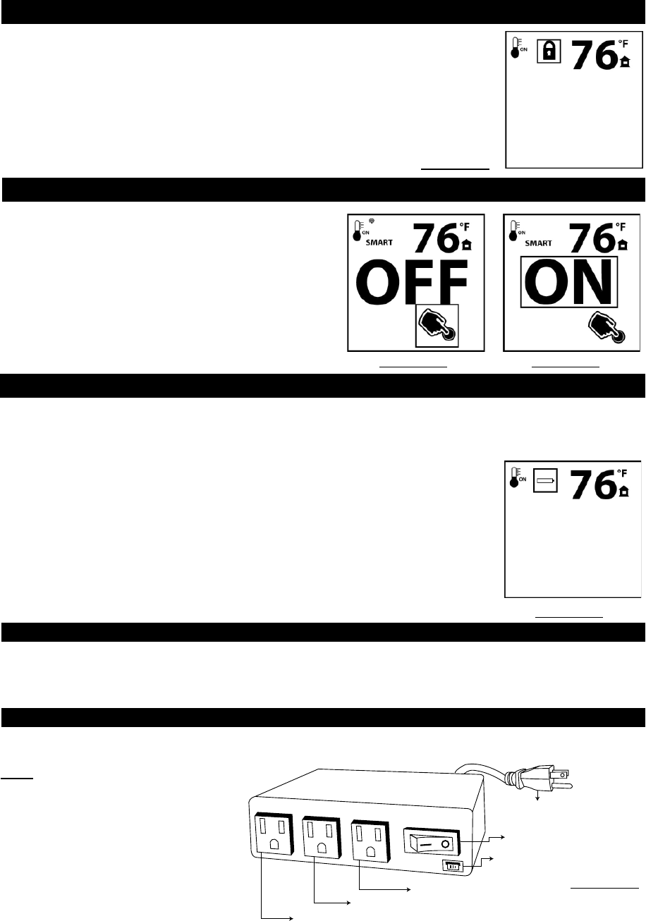
Control Module (CM) offers the added ability to control the fan speed through six (6) speeds, a remotely actuated 120V AUX outlet for the
night light™ and a constantly powered 120V outlet.
NOTE: Control module ON/OFF
switch should always be in the
“ON” position. If for any reason
the module is turned OFF the
components plugged into the
module won’t have power.
CONSTANTLY POWERED
120V OUTLET
FAN OUTLET
120V AUX OUTLET
MAINS VOLTAGE
SUPPLY CORD
MODULE ON/OFF SWITCH
COMMUNICATION BUS (3 PIN)
FIGURE 64
IN THE EVENT OF A POWER FAILURE
CONTROL MODULE
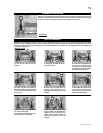
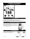
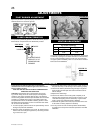
CHILD PROOF FUNCTION
This function will lock the keys to avoid unsupervised operation.
1. Press the MODE and UP keys at the same time.
2. To de-activate this function, press the MODE and UP keys at the same time.
FIGURE 60
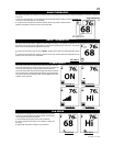
NIGHT LIGHT™
The auxiliary function controls the AUX power outlet on the Control
Module which controls the NIGHT LIGHT™.
1. Use the Mode Key to guide you to the AUX icon.
2. Pressing the Up Arrow Key will activate the NIGHT LIGHT™.
3. Pressing the Down Arrow Key will turn the NIGHT LIGHT™ off.
A single “beep” will confi rm the reception of the command.
FIGURE 61 FIGURE 62