


28
W415-0299 / J / 04.14.08
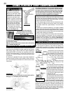
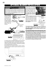
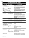
Adjust the pilot screw to provide properly sized fl ame. Turn
in a clockwise direction to reduce the gas fl ow.
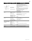
Natural gas models have air shutters set at 1/4 (.250") inch
open. Propane gas models have air shutters set at 7/16
(.437) inch open. Closing the air shutter will cause a more
yellow fl ame, but can lead to carboning. Opening the air
shutter will cause a more blue fl ame, but can cause fl ame
lifting from the burner ports. The fl ame may not appear yellow
immediately; allow 15 to 30 minutes for the fi nal fl ame colour
to be established.
FIGURE 64
FIGURE 62
FIGURE 63
AIR SHUTTER ADJUSTMENT MUST ONLY BE DONE BY
A QUALIFIED GAS INSTALLER!
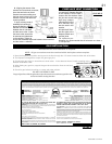
This is a fast acting ther-
mocouple. It is an inte-
gral safety component.
Replace only with a fast
acting thermocouple sup-
plied by Wolf Steel Ltd.
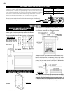
Vertical installations may display a very active fl ame. If this
appearance is not desirable, the vent exit must be restricted
using the optional restrictor vent kit, RP40-KT. This will reduce
the velocity of the exhaust gases, slowing down the fl ame pat-
tern and creating a more traditional gentle appearance.
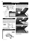
ADJUSTMENTS
PILOT BURNER ADJUSTMENT
VENTURI ADJUSTMENT
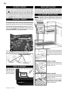
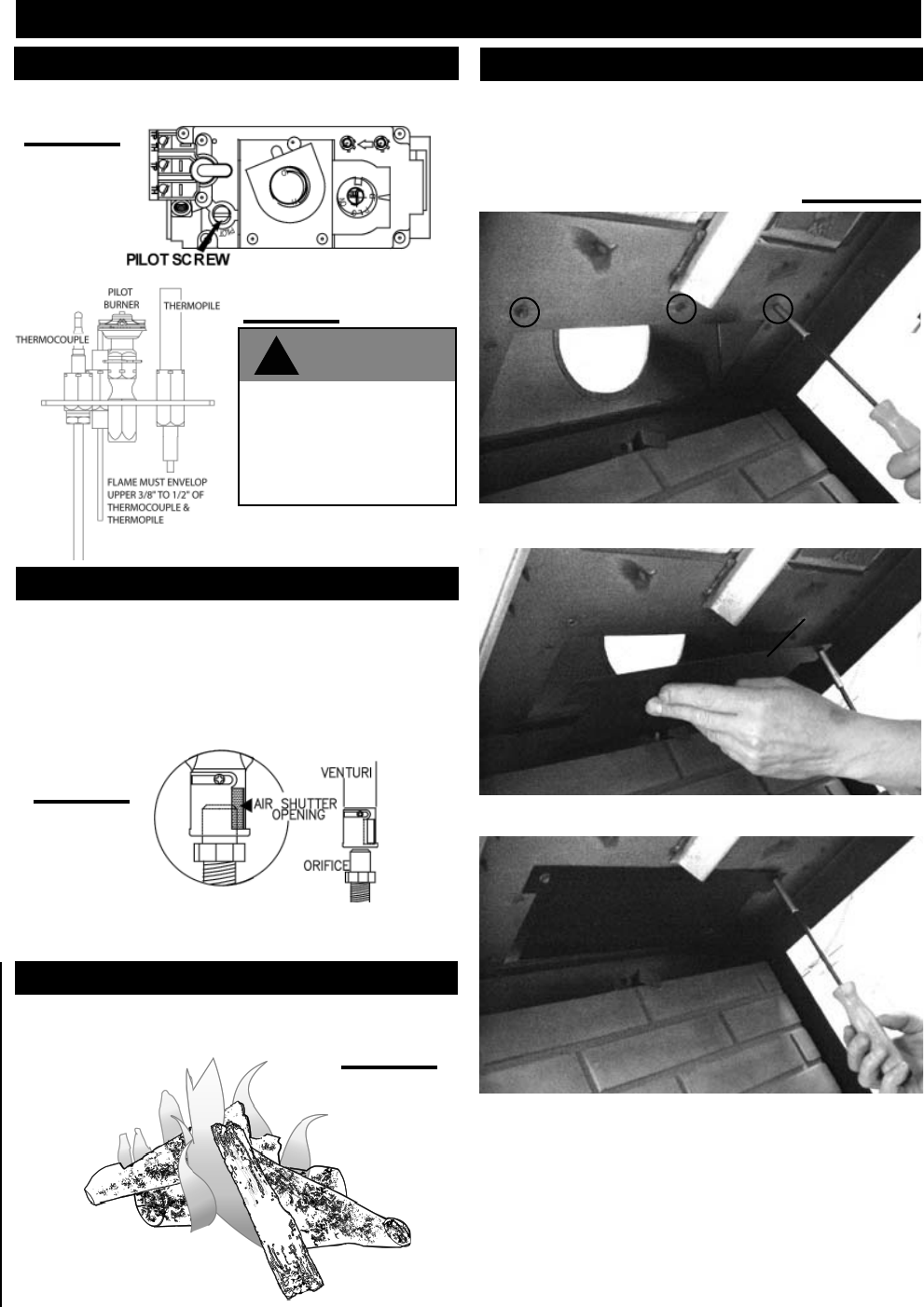
RESTRICTING VERTICAL VENTS
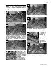
1. Open the glass viewing door.
2. Remove the three screws for mounting the restrictor plate
located in the top of the fi rebox.
SCREWS
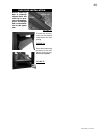
3. Line up the holes on vent restrictor plate with the three
holes from which the screws were removed.
4. Secure the vent restrictor plate into position using the three
screws removed in step 2.
5. Replace the viewing door.
VENT
RESTRICTOR
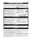
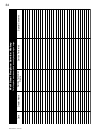
FLAME CHARACTERISTICS
It is important to periodically perform a visual check of the
pilot and burner fl ames. Compare them to the illustrations
provided.
FIGURE 68
FIGURE 65a-c
!
WARNING